Micro-grid system and control method therefor

A technology of micro-grid and mains power, applied in the direction of photovoltaic power generation, electrical components, circuit devices, etc., can solve problems such as micro-grid system instability

Active Publication Date: 2016-05-04
EAST GRP CO LTD
View PDF6 Cites 17 Cited by
  • Summary
  • Abstract
  • Description
  • Claims
  • Application Information

AI Technical Summary

Problems solved by technology

At present, the core problem of the microgrid system is how to reduce the switching impact caused by switching the microgrid system from the grid-connected mode to the island mode so as to ac

Method used


Image

  • Micro-grid system and control method therefor
  • Micro-grid system and control method therefor
  • Micro-grid system and control method therefor

Examples


Embodiment Construction

[0034] In order to explain the microgrid system provided by the present invention more clearly, a specific description will be made below in conjunction with embodiments.

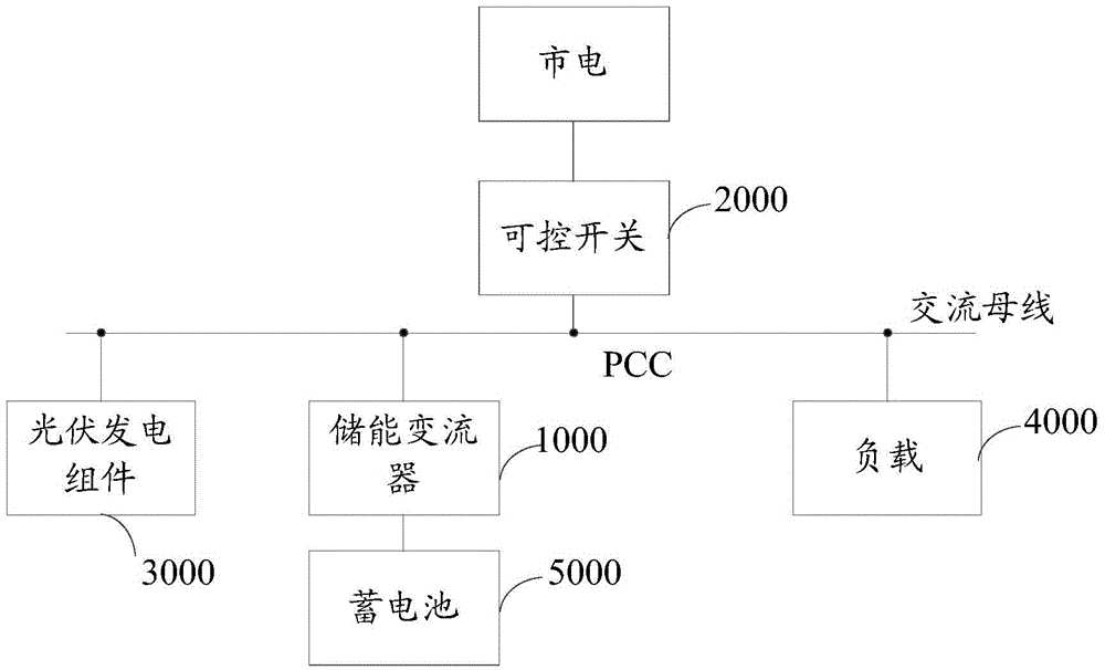
[0035] A microgrid system can work in grid-connected mode and island mode, and its structural diagram is shown in figure 1 shown. The microgrid system includes a battery 5000, an energy storage converter 1000, a controllable switch 2000, a photovoltaic power generation module 3000, a monitoring circuit (not shown in the figure) and a main controller (not shown in the figure). Among them, one end of the controllable switch 2000 is connected to the mains, and the other end is connected to the AC bus through a PCC (Point of Common Connection). One end of the energy storage converter 1000 is connected to the battery, and the other end is connected to the AC bus. The monitoring circuit is connected with the energy storage converter 1000 and the controllable switch 2000 respectively.

[0036] The monitoring ci...


PUM


Abstract

The invention relates to a micro-grid system, which comprises a storage battery, an energy storage converter, a monitoring circuit and a controllable switch. When the micro-grid system is in a grid-connected mode, the energy storage converter outputs a constant power under the control of an inner current loop unit; an outer voltage loop unit does not participate in the control in the grid-connected mode, but is still in an operating state; and the outer voltage loop unit estimates a given current loop signal in advance when the micro-grid system is switched into an island mode from the grid-connected mode according to four input signals of the outer voltage loop unit. When the micro-grid system is switched into the island mode from the grid-connected mode, the outer voltage loop unit is put into operation, and the inner current loop unit controls output voltage and frequency of the energy storage converter to be constant according to the given current loop signal which is estimated in advance and output by the outer voltage loop unit. According to the micro-grid system, the outer voltage loop unit controls the output given current loop signals to be the same before and after the mode is switched, so that seamless switching of the grid-connected mode or the island mode can be achieved. The invention further relates to a control method for the micro-grid system.

Description

technical field [0001] The invention relates to the technical field of power supply, in particular to a microgrid system and a control method thereof. Background technique [0002] A microgrid system is a small distribution subnetwork that includes distributed power generation devices, energy storage converters and loads, and has certain self-regulation and control capabilities. It can operate both in grid-connected mode and in island mode in the event of a grid failure. Microgrid technology has promoted the development of renewable energy utilization and distributed power generation, and has attracted the attention of countries all over the world. [0003] In the micro-grid system, the energy storage converter is the core of the entire micro-grid system, which stores energy in the grid-connected mode, and acts as the main power supply of the micro-grid system in the island mode, providing voltage and frequency for the entire micro-grid system support. At present, the cor...

Claims


Application Information

Patent Timeline
IPC IPC(8): H02J3/38
CPCH02J3/38H02J3/388H02J3/32H02J3/381H02J7/35H02M7/537H02J2300/24H02J2310/10H02M1/0025Y02E10/56Y02P80/14H02J13/00002
Inventor 张涛于玮徐海波苏建徽
Owner EAST GRP CO LTD
Why Eureka
Try Eureka