
Assembly device and assembly method for rotor core

A technology of rotor iron core and assembly device, which is applied in the direction of manufacturing stator/rotor body, etc., can solve the problems of low positioning accuracy of rotor iron core, prone to substandard products, low degree of automation, etc., and achieves stable and reliable moving process and assembly efficiency. High, highly automated effects

Active Publication Date: 2016-05-04
HANGZHOU FUSHENG ELECTRICAL APPLIANCE
View PDF3 Cites 11 Cited by
  • Summary
  • Abstract
  • Description
  • Claims
  • Application Information

AI Technical Summary

Problems solved by technology

[0004] The invention overcomes the disadvantages of low rotor core assembly automation, low rotor core positioning accuracy, low assembly efficiency, and prone to unqualified products, and provides a rotor core assembly device and assembly method, and the rotor core turntable process is automated High degree, high assembly efficiency, precise positioning of the rotor core, rejecting unqualified rotor cores during the assembly process, so that unqualified products are not easy to appear during the assembly process, and the assembly quality is high

Method used


Image

  • Assembly device and assembly method for rotor core
  • Assembly device and assembly method for rotor core
  • Assembly device and assembly method for rotor core

Examples


Embodiment

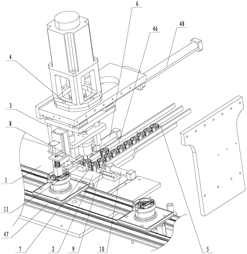
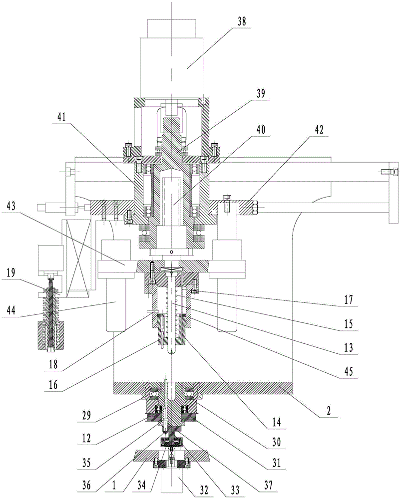
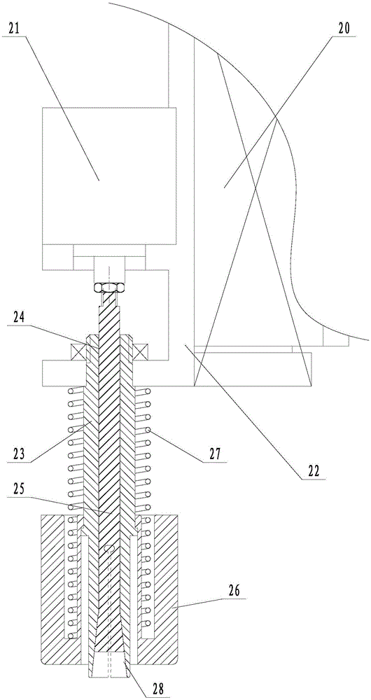
[0023] Embodiment: A rotor core assembly device (see attached Figures 1 to 3 ), including a mounting base 1 installed on the motor rotor assembly line 47, a support plate 2 and a bracket 3 connected to the mounting base, a compression shaping mechanism 4 that can be translated and installed on the bracket, and a feeding channel 5 is provided on the support plate 1. Push out the piston cylinder 6, a liftable turntable 7 is installed on the support plate near one end of the feeding passage, and a fixed shaping head 8 and a moving shaping head 9 are respectively arranged on both sides of the feeding passage on the supporting plate, and the fixed shaping head and the moving shaping head The opposite inner surface of the shaping head is in a concave arc-shaped structure, the fixed shaping head is firmly connected to the support plate, the moving shaping head is connected to the telescopic rod of the feeding piston cylinder 10, and the front end of the telescopic rod of the pushing ...


PUM


Abstract

The invention discloses an assembly device and an assembly method for a rotor core and aims at solving the defect that a disqualified product appears easily due to low assembly automation degree of the rotor core, low positional accuracy of the rotor core and low assembly efficiency. The assembly device comprises a mounting base, a support plate, a support and a compression shaping mechanism, wherein a feed channel and an ejector piston cylinder are arranged on the support plate; a lifting rotary disc is arranged on the support plate; a fixed shaped head and a movable shaped head are arranged on the support plate; the movable shaped head is connected to a feed piston cylinder expansion link; the front end of an ejector piston cylinder expansion link is connected to an ejecting rack; an elastic ejector rod is movably arranged on the rotary disc; a mandrel capable of lifting vertically arranged on the lower end of the compression shaping mechanism; a shaping material return sleeve coats the mandrel; a compression spring coats the mandrel; a plurality of elastic locating core and a plurality of shaping groove shape knives are movably arranged on the shaping material return sleeve; a location sensor is arranged on a position close to the upper ends of the elastic locating cores; and a grab mechanism is arranged at the side of the compression shaping mechanism.

Description

technical field [0001] The invention relates to a rotor core assembly device, more specifically, it relates to a high-efficiency rotor core assembly device and an assembly method. Background technique [0002] The rotor iron core is an important part of the motor. In the process of rotor assembly, it is necessary to assemble the auxiliary balance weight, iron core, magnetic steel, retainer, and main balance weight in sequence. Finally, riveting and blanking are carried out. The iron core is equipped with a magnetic steel installation. Slots and riveting holes for the assembly of magnetic steel and riveting of rivets, so it is necessary to ensure accurate assembly positions during the assembly of the iron core. However, in the prior art, the assembly automation of the rotor core is low, the positioning accuracy of the assembly position is low, the assembly efficiency is low, and unqualified products are prone to appear. [0003] Chinese patent announcement number CN203679703...

Claims


Application Information

Patent Timeline
Patent Type & Authority Applications(China)
IPC IPC(8): H02K15/02
CPCH02K15/02
Inventor 葛明蒋利锋顾正洪王哲
Owner HANGZHOU FUSHENG ELECTRICAL APPLIANCE
Learn More