Pneumatic separation device

A technology of pneumatic separation and separation chamber, which is applied in the direction of solid separation, separation of solid from solid by air flow, chemical instruments and methods, etc., which can solve the problems of inaccurate separation and inability to separate particles of objects with different densities.

Active Publication Date: 2018-12-11
THE UNIV OF NOTTINGHAM NINGBO CHINA
View PDF5 Cites 0 Cited by
  • Summary
  • Abstract
  • Description
  • Claims
  • Application Information

AI Technical Summary

Problems solved by technology

Although this vibratory separation device can separate objects with different densities, when using a sieve for separation, it often needs to be sieved multiple times, and it cannot separate objects with different densities at one time, and the separation is not accurate enough.

Method used


Image

  • Pneumatic separation device

Examples


Embodiment Construction

[0015] Below in conjunction with accompanying drawing and specific embodiment the present invention is described in detail:

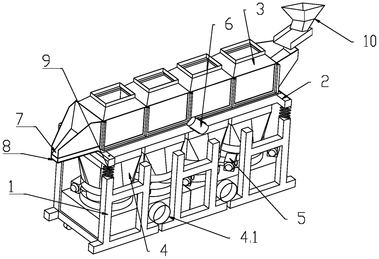
[0016] Such as figure 1 Shown: the present invention provides a kind of pneumatic separation device, and it comprises frame 1, and frame 1 is provided with separation chamber 3, and the top and bottom of separation chamber 3 are all provided with opening, and the bottom of separation chamber 3 is provided with blowing device 4 For blowing air upward from the bottom of the separation chamber 3, the blowing device 4 is provided with a control valve 5 for intermittently starting the blowing device to blow air. The blower 4 adopts a blower or high-pressure gas or other devices capable of blowing. The gas outlet is arranged below the separation chamber 3, and the control valve 5 is a pneumatic butterfly valve controlled by a PLC module.

[0017] After adopting the above structure, the present invention has the following advantages: the present invention ut...


PUM


Abstract

The invention provides a pneumatic separating device. The pneumatic separating device comprises a frame; a separation chamber is arranged on the frame; the top and the bottom of the separation chamber are each provided with an opening; an air blowing device is arranged below the separation chamber and is used for blowing air upwards from the lower portion of the separation chamber; the air blowing device is provided with a control valve which is used for intermittently blowing air. The pneumatic separating device is capable of separating materials different in density by one time. During continuous running of the device, the materials can be layered quite clearly and obviously; therefore, the pneumatic separating device is simple in structure, capable of separating the materials different in density by one time, and quite good in separation effect.

Description

Technical field: [0001] The invention relates to a pneumatic separation device capable of separating object particles with different densities. Background technique: [0002] Vibration separation devices in the prior art include the following types. One is to use a vibrating device to vibrate the filter screen, and through the vibration of the filter screen, the particles with a particle size smaller than the holes of the filter screen will fall below the filter screen, and the particle size is larger than that on the filter screen. The particles in the holes remain on the filter screen, thereby separating objects of different sizes. This vibration separation device can only separate particles according to their size, but cannot separate object particles with different densities. There is also a separation screen, and the vibration device is used to control the swing of the separation screen. When the objects are thrown out, the inertia of objects with different specific gr...

Claims


Application Information

Patent Timeline
Patent Type & Authority Patents(China)
IPC IPC(8): B07B9/00B07B1/28B07B4/08B07B11/02B07B11/04
CPCB07B1/28B07B4/08B07B9/00B07B11/02B07B11/04
Inventor 菲利普赫尔王筝顾复尼克迈尔斯
Owner THE UNIV OF NOTTINGHAM NINGBO CHINA
Why Eureka
Try Eureka