
Drill press with a quick drilling apparatus

A drilling machine, fast technology, applied in the direction of drilling/drilling equipment, parts of boring machine/drilling machine, metal processing equipment, etc., can solve the problem of increasing the risk of the operator's work

Inactive Publication Date: 2016-05-11
REXON IND CORP LTD
View PDF10 Cites 0 Cited by
  • Summary
  • Abstract
  • Description
  • Claims
  • Application Information

AI Technical Summary

Problems solved by technology

Although the use of this drive unit can achieve the purpose of saving labor and speed, but because the large chainring, small chainring, chain and other components are exposed, the work risk of the operator will be increased.

Method used


Image

  • Drill press with a quick drilling apparatus
  • Drill press with a quick drilling apparatus
  • Drill press with a quick drilling apparatus

Examples


Embodiment Construction

[0019] Below in conjunction with accompanying drawing and embodiment the present invention is described in detail:

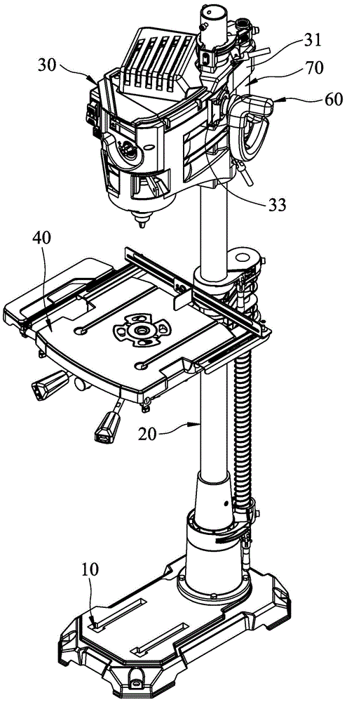
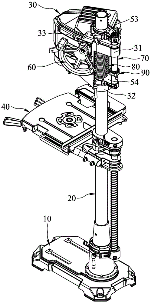
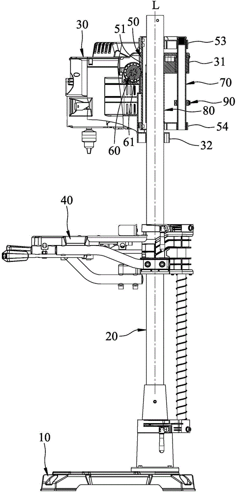
[0020] refer to figure 1 , figure 2 and image 3 , an embodiment of the drill press that can be drilled quickly in the present invention includes a base 10, a guide column 20, a head unit 30, a workbench 40, a locking unit 50, a driving unit 60, a guide Lead rod 70 , a return spring 80 and a depth positioning adjustment member 90 .

[0021] The base 10 can be stably fixed on the ground.

[0022] The guide post 20 is fixed on the base 10 and extends along an axis L. As shown in FIG.

[0023] The head unit 30 can be lifted and connected to the top of the guide post 20, and has an upper fitting part 31 that can slide and is sleeved on the guide post 20, and an upper fitting part 31 that is spaced apart from the upper fitting part 31 and can slide and The lower fitting portion 32 of the guide post 20 is sheathed on and a shaft seat 33 corresponding to the guid...


PUM


Abstract

A drill press with a quick drilling apparatus includes a base, a column, a head assembly which can move upwards and downwards along with the column and connect to the top of the column, a table assembly connected to the column, a fastening assembly secured on the column corresponding to the head assembly and a driving assembly, wherein the fastening assembly has a plurality of discontinuous and spaced engaging teeth which can be engaged with corresponding engaging holes and the driving assembly has a driving wheel engaged with the fastening assembly and an operating part connected with the driving wheel. The driving wheel has a plurality of discontinuous and spaced engaging teeth which can be engaged with the corresponding engaging holes separately. Using the operating part to drive the driving wheel to rotate along with the fastening assembly and using the coordination between the engaging teeth and engaging holes can achieve the quick drilling operation.

Description

technical field [0001] The invention relates to a processing tool, in particular to a drilling machine capable of rapid drilling. Background technique [0002] An existing drilling machine can drive a machine head unit to move up and down along a guide column and relative to a worktable, so as to achieve the purpose of drilling in and out. [0003] And the general lifting structure of the head unit is that a tooth row is fixed on the side of the guide column, and a gear that can be engaged with the tooth row is arranged on the inner shaft of the head unit, and a gear is installed outside the head unit. There is an operating handle that can link the gear. Because of the meshing relationship between the gear and the gear row, when the drilling depth is deep, the operator needs to pause after turning the operating handle at an appropriate angle before continuing to turn the operating handle for several consecutive circles to achieve continuous drilling. The purpose of drillin...

Claims


Application Information

Patent Timeline
Patent Type & Authority Applications(China)
IPC IPC(8): B23B35/00B23B47/18B23B47/00
Inventor 郑志明杨乔安
Owner REXON IND CORP LTD
Learn More