Milling cutter

A technology of milling cutters and blades, which is applied in the field of forming milling cutters, can solve the problems of complex contour lines of cutting blades, reducing the service life of forming milling cutters, easy wear or cracking of blades, etc. Avoid the effect of chattering

Inactive Publication Date: 2016-05-11
JIZHUN PRECISION IND HUIZHOU
View PDF5 Cites 6 Cited by
  • Summary
  • Abstract
  • Description
  • Claims
  • Application Information

AI Technical Summary

Problems solved by technology

Therefore, when the contour line of the workpiece to be obtained is long, at the moment of milling with the traditional form milling cutter, because the blade has to cut into the workpiece at one time and remove the workpiece material to form the arc surface contour of the workpiece, the cutting resistance will be relatively large, which is easy to cause Vibration milling produces vibration tool marks on the workpiece, which affects the processing quality of the workpiece
In addition, when the contour shape of the workpiece contour line to be obtained is relatively complex, the corresponding cutting edge blade contour line is also relatively complex, and the cutting resistance it bears during processing is relatively greater, and the blade is more likely to wear or crack, reducing the wear and tear of the forming milling cutter. service life

Method used


Image

  • Milling cutter
  • Milling cutter
  • Milling cutter

Examples


Embodiment Construction

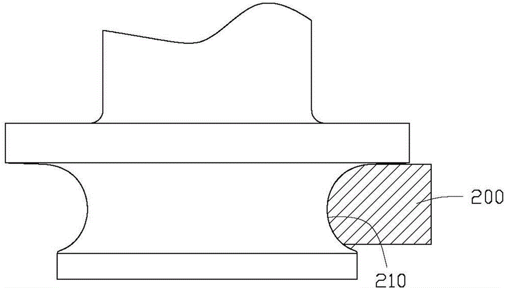
[0032] see Figure 2 to Figure 6 , the milling cutter 100 of the first embodiment of the present invention is used to process the workpiece 200 (see reference Figure 5 ) to perform milling, and process the workpiece 200 into a predetermined outer contour. Specifically, the workpiece 200 is roughly plate-shaped (not shown in the figure), the outer contour is formed around the edge of the workpiece 200 , and the cross-section of the outer contour is roughly an arc-shaped contour line 210 . Further, the outline 210 includes a first portion 212 and a second portion 214 continuous with the first portion 212 . In this embodiment, both the first portion 212 and the first portion 212 are partially arc-shaped.

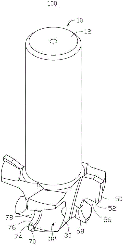
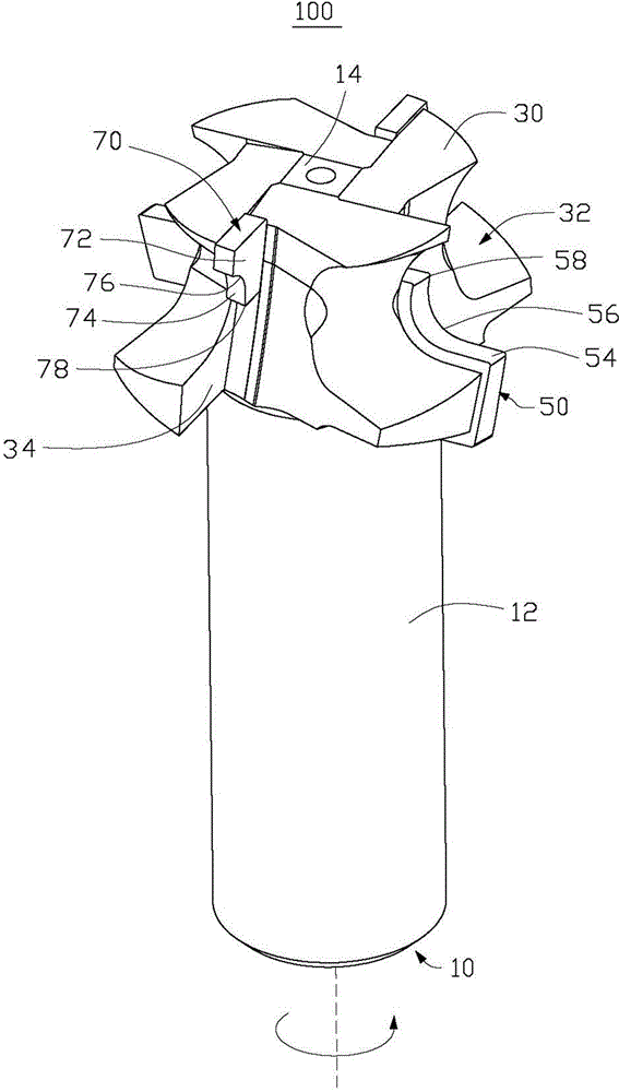
[0033] see again figure 2 , The milling cutter 100 includes a handle 10 , a blade supporting portion 30 mounted on the handle 10 , and a first blade 50 and a second blade 70 mounted on the blade supporting portion 30 .

[0034] The handle 10 is substantially cylindrical a...


PUM


Abstract

The invention provides a milling cutter used for machining a workpiece to obtain a predetermined contour line. The predetermined contour line comprises a first part and a second part connected with the first part. The milling cutter comprises a cutter handle provided with a center shaft and further comprises a plurality of first cutting edges and a plurality of second cutting edges, wherein the first cutting edges and the second cutting edges are arranged in a stagger mode, the first cutting edges are used for rotating around the center shaft to form a first rotation track to machine the first part of the predetermined contour line of the workpiece, the second cutting edges are used for rotating around the center shaft to form a second rotation track different from the first rotation track to machine the second part of the predetermined contour line of the workpiece, and the first rotation track is connected with the second rotation track. The milling cutter is relatively low in cutting resistance and long in service life.

Description

technical field [0001] The invention relates to a milling cutter, in particular to a form milling cutter for machining the contour of a workpiece. Background technique [0002] In the industry, a form milling cutter is often used to mill the side of the workpiece to form the required arc surface profile on the workpiece. The traditional form milling cutter uses a profiling blade adapted to the contour of the arc surface to process the above-mentioned workpiece. The contour line of the cutting edge of the blade is the same shape and length as the contour line to be processed (see figure 1 ). Therefore, when the contour line of the workpiece to be obtained is long, at the moment of milling with the traditional form milling cutter, because the blade has to cut into the workpiece at one time and remove the workpiece material to form the arc surface contour of the workpiece, the cutting resistance will be relatively large, which is easy to cause Vibration milling produces vibra...

Claims


Application Information

Patent Timeline
Patent Type & Authority Applications(China)
IPC IPC(8): B23C5/16B23C5/28
CPCB23C3/12B23C5/1081B23C5/14B23C2210/242B23C2210/285B23C2210/287
Inventor 李军旗蒋益民徐龙占立峰
Owner JIZHUN PRECISION IND HUIZHOU
Why Eureka
Try Eureka