Electric control air flow driving mechanical grinding machine

A technology of airflow drive and airflow tube, which is applied in the direction of grinding drive devices, manufacturing tools, and grinding machine parts, etc. It can solve the problems of motor jamming, grinder grinding, motor burnout, etc., and achieves simple structure and design. Scientific and reasonable, easy to use effect

Inactive Publication Date: 2016-05-11
HEILONGJIANG KANGGEER TECH
View PDF0 Cites 1 Cited by
  • Summary
  • Abstract
  • Description
  • Claims
  • Application Information

AI Technical Summary

Problems solved by technology

[0003] The commonly used grinders on the market are driven by motors, which are often limited by power supply. When the workshop is powered off or there is no cable, it is impossible to use the grinder for grinding. Moreover, if the grinder is driven by a motor, when the workpiece is not ground due to voltage When the grinding wheel is stuck, it will cause the motor to be stuck and cause the motor to burn out

Method used


Image

  • Electric control air flow driving mechanical grinding machine
  • Electric control air flow driving mechanical grinding machine
  • Electric control air flow driving mechanical grinding machine

Examples


Embodiment Construction

[0016] The present invention will be further described below in conjunction with accompanying drawing and example.

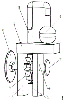
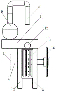
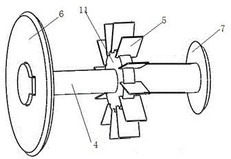
[0017] like figure 1 , figure 2 and image 3 As shown, an electrically controlled airflow-driven mechanical grinder, its structure includes: mounting base 1, right support plate 2, left support plate 3, grinding wheel rotating shaft 4, airflow driving blade 5, large grinding wheel 6, small grinding wheel 7 , power air flow pipe 8, high-pressure gas cylinder 9, protective cover 10, impeller mounting plate 11, air flow control valve 12, the mounting seat 1 is fixed on the left support plate 3 and the right support plate 2, and the grinding wheel rotating shaft 4 is installed On the left support plate 3 and the right support plate 2 and the grinding wheel rotating shaft 4 passes through the left supporting plate 3 and the right supporting plate 2, one end of the grinding wheel rotating shaft 4 is installed with a large grinding wheel 6, and the other end of the ...


PUM


Abstract

The invention discloses an electric control air flow driving mechanical grinding machine, and belongs to the technical field of electric machinery manufacturing. An installing seat is fixed on a left support plate and a right support plate; a grinding wheel rotating shaft is arranged on the left support plate and the right support plate and penetrates through the left support plate and the right support plate; one end of the grinding wheel rotating shaft is provided with a large grinding wheel; the other end of the grinding wheel rotating shaft is provided with a small grinding wheel; an impeller installing disc is arranged in the middle position of the grinding wheel rotating shaft; air flow driving blades are arranged on the impeller installing disc; a power air flow pipe is arranged on the installing seat arranged right above the air flow driving blades, and is connected with a high-pressure air storage cylinder; and the tail end of the power air flow pipe is provided with an air flow control valve. The electric control air flow driving mechanical grinding machine has the advantages that the design that the airflow driving blades are arranged on the grinding wheel rotating shaft, and the air flow driving blades are impacted by high-pressure air flow is used, so that the goal of driving the grinding wheel rotating shaft is achieved; the high-speed rotation of the large grinding wheel and the small grinding wheel can be realized; and the problem of burnt damage of the motor due to seizurewhen the motor driving modeis used can be avoided.

Description

technical field [0001] The invention relates to an electrical control mechanical device, in particular to an electrical control airflow driven mechanical grinder, which belongs to the technical field of electrical control machinery. Background technique [0002] In the process of mechanical manufacturing, it is often necessary to grind machine tools, parts surfaces, casting corners, etc. At present, the longest grinding process is a grinder. The existing grinder does not use a motor-driven grinding wheel for grinding. Mainly use the high-speed rotation of the motor to drive the high-speed rotation of the grinding wheel to achieve the purpose of grinding the workpiece. [0003] The commonly used grinders on the market are driven by motors, which are often limited by power supply. When the workshop is powered off or there is no cable, it is impossible to use the grinder for grinding. Moreover, if the grinder is driven by a motor, when the workpiece is not ground due to voltage...

Claims


Application Information

Patent Timeline
Patent Type & Authority Applications(China)
IPC IPC(8): B24B47/14
Inventor 不公告发明人
Owner HEILONGJIANG KANGGEER TECH
Why Eureka
Try Eureka