Periscopic imaging holder

A periscope and imaging technology, applied in image communication, machine/bracket, TV, etc., can solve the problems of poor anti-interference ability and low stability of imaging system, so as to increase stability, reduce overturning moment, and improve stability sexual effect

Pending Publication Date: 2022-02-08
CONVERGENCE TECH CO LTD
View PDF4 Cites 0 Cited by
  • Summary
  • Abstract
  • Description
  • Claims
  • Application Information

AI Technical Summary

Problems solved by technology

[0005] Aiming at at least one of the above defects or improvement needs of the prior art, such as the problems of low stability and poor anti-interference ability of the traditional imaging pan / tilt in the imaging system, especially when the optical tube length of the imaging system is longer, the present invention A periscope imaging platform is provided. The optical movement includes a series of structures such as reflective elements, lenses, focusing mechanisms, and image sensors, forming a horizontal arrangement of reflective light paths and barrel lengths. When the lens is a telephoto lens, its barrel length is usually Greater than its width or diameter, when the rotation axis of the first rotation mechanism is parallel to or coincident with the optical axis of the lens, the optical core can obtain a shorter rotation force arm and a smaller moment of inertia when the optical core rotates around the rotation axis, and a shorter rotation force arm The stability can be greatly increased, and the smaller moment of inertia can reduce the torque requirement for the first rotating mechanism, which is convenient for high-speed rotation and is also conducive to the miniaturization of the first rotating mechanism. The same is true for the second rotating mechanism

Method used


Image

  • Periscopic imaging holder
  • Periscopic imaging holder
  • Periscopic imaging holder

Examples


Embodiment Construction

[0047]In order to make the object, technical solution and advantages of the present invention clearer, the present invention will be further described in detail below in conjunction with the accompanying drawings and embodiments. It should be understood that the specific embodiments described here are only used to explain the present invention, not to limit the present invention. In addition, the technical features involved in the various embodiments of the present invention described below can be combined with each other as long as they do not constitute a conflict with each other. The present invention will be further described in detail below in combination with specific embodiments.

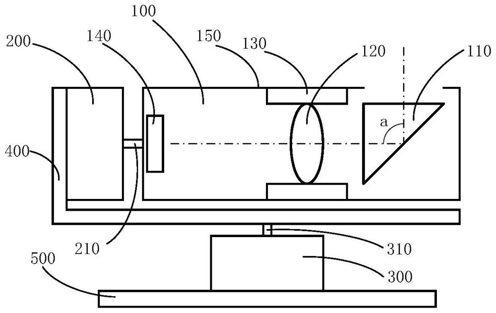
[0048] The first embodiment of the present invention is as figure 1 As shown, a periscope imaging platform is provided. It includes an optical core 100 , a first rotating mechanism 200 , a second rotating mechanism 300 , an adapter bracket 400 and a base 500 . The optical movement 100 incl...


PUM


Abstract

The invention discloses a periscopic imaging holder, and the imaging holder is characterized in that the imaging holder comprises an optical movement, a first rotating mechanism, an adapter bracket and a second rotating mechanism which are connected in sequence; the optical movement comprises a reflecting element, a first imaging lens, a focusing mechanism and a first image sensor which are arranged in sequence; the reflecting element enables the light to generate angle turning; the rotating shaft of the first rotating mechanism is parallel to or coincides with the optical axis of the first imaging lens, and the rotating shafts of the first rotating mechanism and the second rotating mechanism are perpendicular to each other. Transverse arrangement of a reflection light path and the barrel length is formed, when the lens is in a long focus and the optical movement rotates around the rotating shaft, a shorter rotating force arm and smaller rotating inertia can be obtained, the shorter rotating force arm can greatly improve the stability, the smaller rotating inertia can reduce the torque requirement for the first rotating mechanism, high-speed rotation can be conveniently achieved, the the miniaturization of the first rotating mechanism is facilitated, and the second rotating mechanism is similar.

Description

technical field [0001] The invention belongs to the field of imaging equipment, and in particular relates to a periscope imaging platform. Background technique [0002] The field of view of the imaging system is limited, and it is a common method to use a pan-tilt to cooperate with the imaging system to form an imaging pan-tilt to increase the field of view. For example, Chinese patent CN201821029334.1 and Chinese patent CN201721429153.3 each provide a pan-tilt camera, and Chinese patent CN201620356018.X provides a pan-tilt for latitude and longitude matching telescopes. After the imaging system is equipped with a pan / tilt, it can also obtain an angle measurement function. For example, Chinese patent CN201921296755.5 provides an electronic theodolite with imaging function. [0003] In order to realize large-scale imaging, the gimbal needs two axes, and the three axes formed by these two axes and the optical axis of the imaging system need to be orthogonal to each other. Wh...

Claims


Application Information

Patent Timeline
Patent Type & Authority Applications(China)
IPC IPC(8): H04N5/225H04N5/232F16M11/04F16M11/12F16M11/18
CPCF16M11/045F16M11/12F16M11/18H04N23/54H04N23/55H04N23/67H04N23/695
Inventor 胡庆磊黄凯李宁李梦婷丁昶杰杨旭
Owner CONVERGENCE TECH CO LTD
Why Eureka
Try Eureka