Detaching roller driving mechanism for combing machine and driving method of detaching roller driving mechanism
A technology for separating rollers and drive mechanisms, applied in combers, textiles and papermaking, fiber processing, etc., can solve the problems of high noise and vibration, low motion accuracy, and large number of components, and achieve the requirements of reducing synchronization and reducing Moment of inertia, effect of simplified mechanical transmission
- Summary
- Abstract
- Description
- Claims
- Application Information
AI Technical Summary
Problems solved by technology
Method used
Image
Examples
Embodiment 1
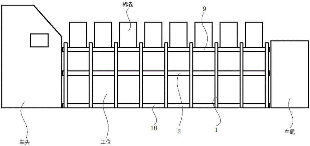
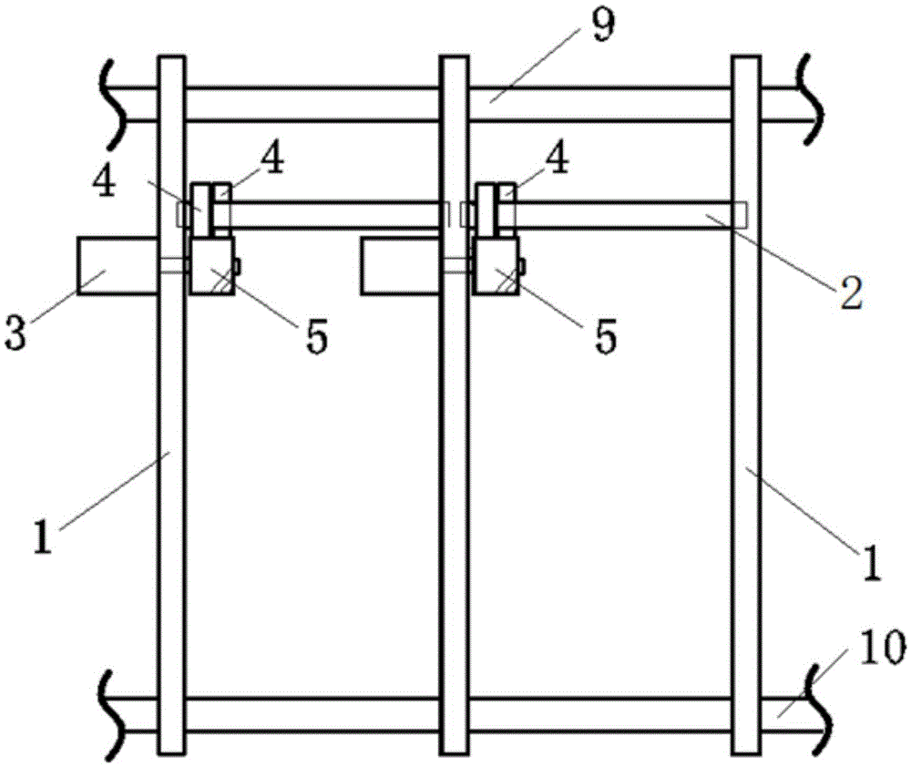
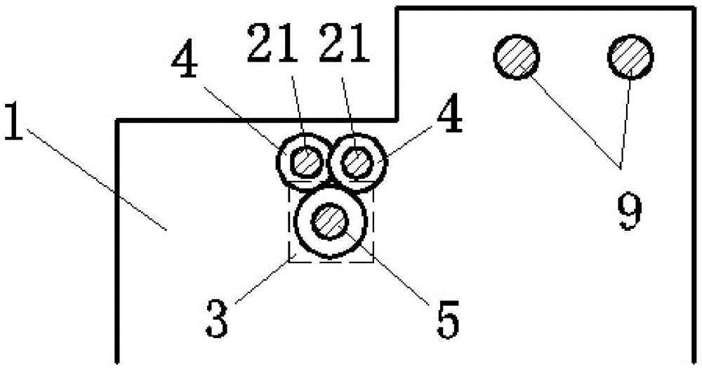
[0061] Such as figure 2 and image 3 As shown, the distributed driving mechanism of the detaching rollers of the combing machine in this embodiment includes: a combing machine support 1 , a detaching roller part 2 and a servo motor 3 . Wherein, the upper support shaft 9 is arranged on the top of the comber support 1, and the lower support shaft 10 is arranged at the bottom, and the separating roller part 2 is supported on the comber support 1 by the bearings provided at its two ends. Eight detaching roller sections 2 are distributed on the comber support 1 . Each detaching roller part 2 includes two detaching rollers 21 arranged horizontally side by side; each detaching roller part 2 is driven by an independent servo motor 3 .
[0062] In this embodiment, the detaching rollers 21 of different detaching roller parts 2 face each other end to end, so that the detaching roller parts 2 are arranged in a line.
[0063] In this embodiment, the servo motor 3 drives the roller gear...
Embodiment 2
[0075] Such as Figure 4 and Figure 5 As shown, the distributed drive mechanism for the detaching rollers of the combing machine in this embodiment includes a combing machine support 1 , a detaching roller part 2 and a servo motor 3 .
[0076] The difference between this embodiment and embodiment 1 is:
[0077] The output shaft of the servo motor 3 in the present embodiment is provided with the motor shaft gear 31, is connected with the idle gear 5 by the motor shaft gear 31 by two servo motors 3, and the servo motor 3 drives the roller gear 4 through the idle gear 5.
[0078] In the present embodiment, the roller gear 4, the motor shaft gear 31 and the idler gear 5 are close to one side of the comber support 1; the servo motor 3 is arranged on the other side of the comber support 1, and the servo motor 3 is arranged on a separate Below the roller part 2.
[0079] In this embodiment, the separating roller 21 has a diameter of 20mm and a length of 600mm; the roller gear 4 h...
Embodiment 3
[0085] Such as Figure 6 and Figure 7 As shown, the distributed drive mechanism for the detaching rollers of the combing machine in this embodiment includes a combing machine support 1 , a detaching roller part 2 and a servo motor 3 .
[0086] The difference between this embodiment and embodiment 1 is:
[0087] In this embodiment, the output shaft of the servo motor 3 is provided with a motor shaft pulley 6 , and the pulley drives the roller gear 4 through a synchronous belt 7 .
[0088] In this embodiment, a tension pulley 8 is also included, and a plurality of tension pulleys 8 are closely attached to the outer side of the synchronous belt 7 .
[0089] In this embodiment, the number of the servo motors 3 of the detaching roller part 2 is two, and the driving form of the detaching roller 21 is driven by the synchronous belt 7 .
[0090] In this embodiment, the servo motor 3 can be arranged at any position below the separating roller part 2, avoiding space interference wit...
PUM
| Property | Measurement | Unit |
|---|---|---|
| diameter | aaaaa | aaaaa |
| length | aaaaa | aaaaa |
| diameter | aaaaa | aaaaa |
Abstract
Description
Claims
Application Information
 - R&D
- Intellectual Property
- Life Sciences
- Materials
- Tech Scout
- Unparalleled Data Quality
- Higher Quality Content
- 60% Fewer Hallucinations
Browse by: Latest US Patents, China's latest patents, Technical Efficacy Thesaurus, Application Domain, Technology Topic, Popular Technical Reports.
© 2025 PatSnap. All rights reserved.Legal|Privacy policy|Modern Slavery Act Transparency Statement|Sitemap|About US| Contact US: help@patsnap.com


