
Four-valve cylinder cover for lightweight engine

A cylinder head and engine technology, which is applied to engine components, machines/engines, cylinder heads, etc., can solve the problems of affecting intake efficiency, limiting the degree of engine strengthening, and low cooling water flow and flow rate in the nose bridge area of ​​the cylinder head. The effect of improving cooling efficiency and avoiding the problem of lubricating oil aging

Inactive Publication Date: 2016-05-11
WEICHAI POWER YANGZHOU DIESEL ENGINE
View PDF7 Cites 4 Cited by
  • Summary
  • Abstract
  • Description
  • Claims
  • Application Information

AI Technical Summary

Problems solved by technology

Cylinder heads with traditional structures cannot meet the requirements of future high-power-density, highly-strengthened light-duty engines in terms of performance and reliability
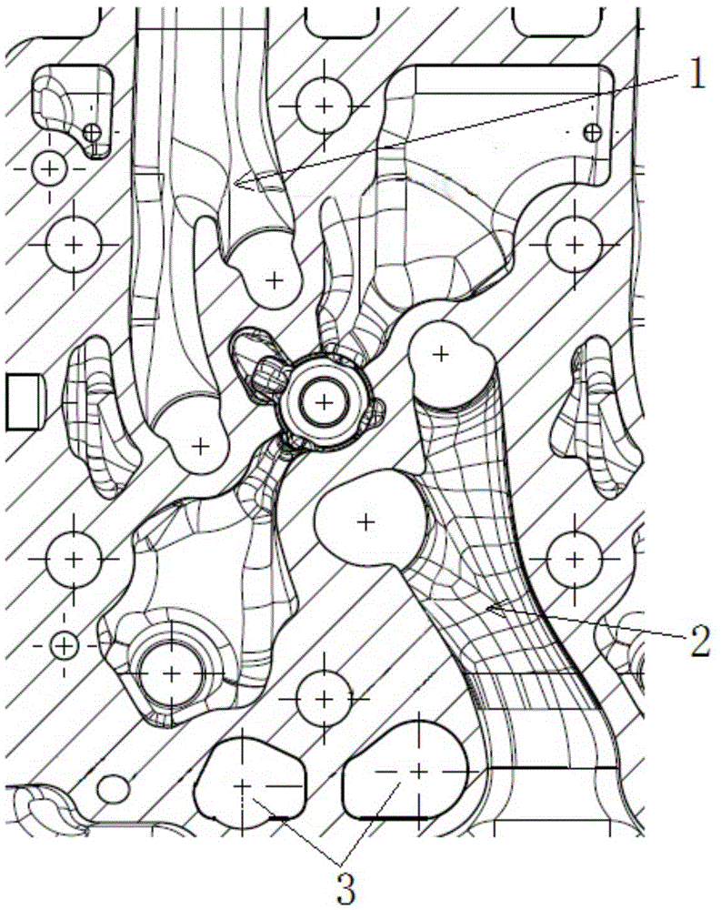
[0003] The intake port of the four-valve cylinder head of the current light engine generally adopts a combined intake port structure, with one intake port 1 for each cylinder, such as figure 1 As shown, in the intake process, there will be mutual interference between the two intake channels, which will affect the intake efficiency; at present, the cylinder head push rod hole 3 of the side camshaft is generally located on the side of the exhaust port 2, and the lubricating oil flows through the exhaust side Easy to cause aging in high temperature zone
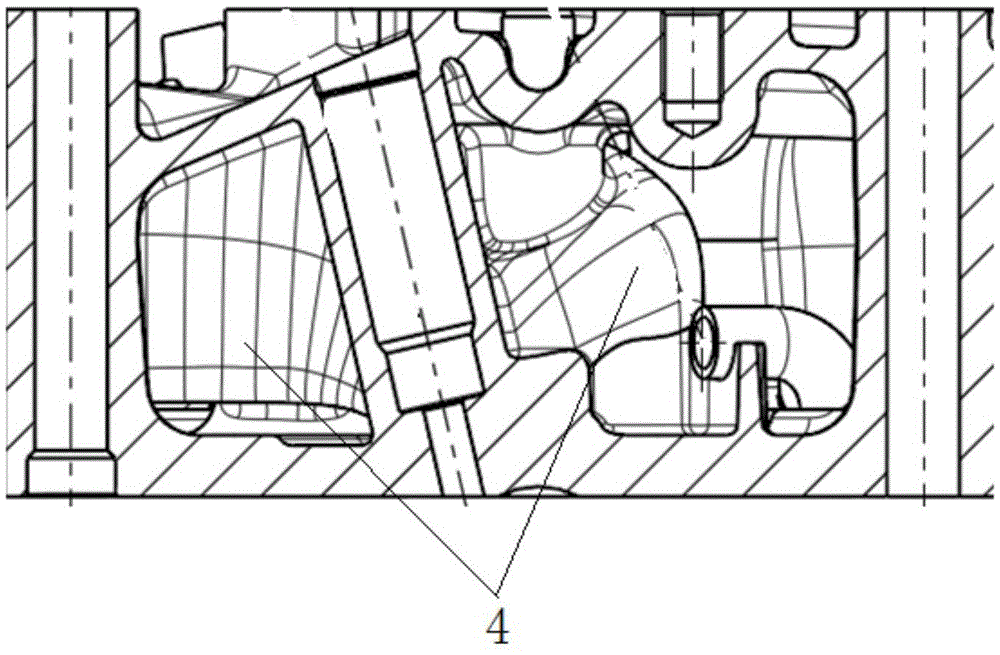
like figure 2 As shown, the cylinder head cooling water jacket 4 of the existing light-duty engine generally adopts a non-layered structure, resulting in a low flow rate and flow rate of the cooling water flowing through the nose bridge area of ​​the cylinder head, and a high cooling efficiency cannot be obtained.
At the same time, the existing light-duty cylinder head adopts no partition and vertical plate structure, the structural strength is low, and the maximum explosion pressure it can withstand is limited, which limits the improvement of the engine's strengthening degree

Method used


Image

  • Four-valve cylinder cover for lightweight engine
  • Four-valve cylinder cover for lightweight engine
  • Four-valve cylinder cover for lightweight engine

Examples


Embodiment Construction

[0025] The specific implementation manners of the present invention will be further described in detail below in conjunction with the accompanying drawings and embodiments. The following examples are used to illustrate the present invention, but are not intended to limit the scope of the present invention.

[0026] In the description of the present invention, it should be noted that the terms "center", "longitudinal", "transverse", "upper", "lower", "front", "rear", "left", "right", " The orientations or positional relationships indicated by "vertical", "horizontal", "top", "bottom", "inner", "outer", etc. are based on the orientation or positional relationships shown in the drawings, and are only for the convenience of describing the present invention and simplifying Describes, but does not indicate or imply that the device or element referred to must have a specific orientation, be constructed in a specific orientation, and operate in a specific orientation, and therefore sh...


PUM


Abstract

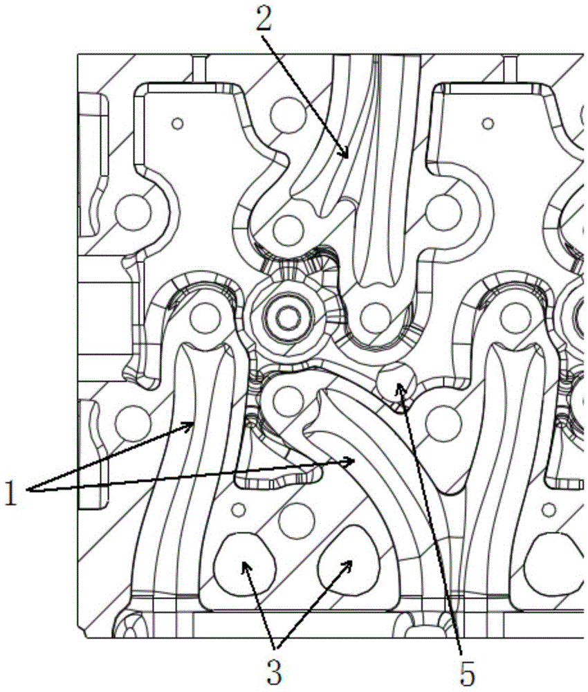
The invention relates to the technical field of diesel cylinders and discloses a four-valve cylinder cover for a lightweight engine. Push rod holes and water jackets are arranged in the cylinder cover; air inlet channels are formed in one side of the cylinder cover; air exhaust channels are formed in the other side of the cylinder cover; the interior of the cylinder cover is divided into four partition cylinders; the water jackets include an upper water jacket and lower water jackets; the upper water jacket is arranged on the upper side in the cylinder cover; the lower water jackets are arranged on the lower side in the cylinder cover; a water channeling hole for communicating the upper water jacket and the lower water jackets is formed between the upper water jacket and the lower water jackets; two adjacent partition cylinders share one air inlet channel; and the push rod holes are arranged close to the corresponding air inlet channels. The four-valve cylinder cover can prevent intake flows from mutually interfering so as to improve the air inlet efficiency, can prevent the ageing problem of lubricating oil and can also improve the cooling efficiency.

Description

technical field [0001] The invention relates to the technical field of diesel engine cylinders, in particular to a light-duty engine four-valve cylinder head. Background technique [0002] As power increases and emissions upgrade, light-duty engines are increasingly thermally loaded and hardened. Cylinder heads with traditional structures cannot meet the requirements of future high power density, highly reinforced light-duty engines in terms of performance and reliability. [0003] The intake port of the four-valve cylinder head of the current light engine generally adopts a combined intake port structure, with one intake port 1 for each cylinder, such as figure 1 As shown, in the intake process, there will be mutual interference between the two intake channels, which will affect the intake efficiency; at present, the cylinder head push rod hole 3 of the side camshaft is generally located on the side of the exhaust port 2, and the lubricating oil flows through the exhaust s...

Claims


Application Information

Patent Timeline
IPC IPC(8): F02F1/42F02F1/36
CPCF02F1/4221F02F1/36
Inventor 张伟刚吕顺吴雪雷韩景峰贺园玲
Owner WEICHAI POWER YANGZHOU DIESEL ENGINE
Features
  • Generate Ideas
  • Intellectual Property
  • Life Sciences
  • Materials
  • Tech Scout
  • Unparalleled Data Quality
  • Higher Quality Content
  • 60% Fewer Hallucinations
Learn More