Fluid switch valve

A fluid switch and valve seat technology, which is applied in the direction of valve lift, valve details, valve device, etc., can solve the problems of large fluid kinetic energy loss, large switch driving torque, and flow velocity disorder, and achieve small flow area difference and on-off control The effect of small force and small loss of kinetic energy

Inactive Publication Date: 2016-05-11
牛奔田
View PDF8 Cites 8 Cited by
  • Summary
  • Abstract
  • Description
  • Claims
  • Application Information

AI Technical Summary

Problems solved by technology

[0003] The existing valves adopt the method of directly opening or closing the flow channel to realize the switch control of the fluid, such as: gate valve and gate valve, the switch driving torque is large, and the opening and closing must be controlled by a screw, and the opening and closing time is lon

Method used


Image

  • Fluid switch valve

Examples


Embodiment Construction

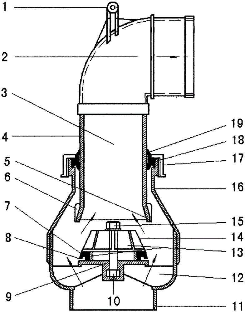
[0009] exist figure 1 , the handle (1), elbow (2) and valve pipe (3) are fixedly connected together. The base (11) and the valve outer pipe (16) are fixedly connected together. The sealing seat (9) is fixedly connected with the base (11) through the bracket (12), and the conical fixed cover (13) and sealing ring (7) are fixed on the valve seat ( 9) on. The screw cover (17) fixes the two-way sealing ring (19) in the sealing groove (18) at the top of the outer tube (16) of the valve to form a leak-proof seal. The conical fixed cover (13) is in the shape of a truncated cone, and its function is to fix the sealing ring (7). When the valve pipe (3) moves downward, the sealing port (5) is guided by the conical inclined surface (14), so that the sealing The ring (7) enters the sealing port (5) smoothly.

[0010] Closing process: press the handle (1) downward, the valve pipe (3) moves downward, guided by the tapered surface (14) of the tapered fixed cover (13), the sealing ring (7...


PUM


Abstract

Provided is a fluid switch valve. The fluid switch valve is composed of a handle, a bend, a valve pipe, a sealing opening, a sealing ring, a valve seat, a base, a bracket, a conical fixing cover, a valve external pipe, a bidirectional sealing ring and the like. The valve pipe can horizontally rotate and move up and down in the valve external pipe. The valve pipe is a part of a runner and also a part of the valve. On-off switch control over fluid is achieved through the sealing opening of the valve pipe and the sealing ring of the valve seat. When the handle is pressed down, the sealing ring enters the sealing opening, and thus the fluid is cut off. When the handle is pulled up, the sealing opening is disengaged from the sealing ring, and hence the fluid flows out through the valve pipe and the bend.

Description

Technical field [0001] The invention relates to a valve device for connecting or cutting off fluid in a pipeline system. Background technique [0002] Known valves for controlling fluid on-off mainly include cut-off gates, gates, butterflies, and spheres in structure, such as stop valves, gate valves, butterfly valves, and ball valves. [0003] The existing valves adopt the method of directly opening or closing the flow channel to realize the switch control of the fluid, such as: gate valve and gate valve, the switch driving torque is large, and the opening and closing must be controlled by a screw, and the opening and closing time is long; the butterfly valve The valve plate of the valve is seriously blocked in the fluid, the local flow velocity is turbulent, and the kinetic energy of the fluid is lost; the ball valve requires high processing precision, and it is not suitable to be made into a valve that can control a large flow of fluid. Contents of the invention [000...

Claims


Application Information

Patent Timeline
IPC IPC(8): F16K1/00F16K1/36F16K1/46F16K31/60
CPCF16K1/00F16K1/36F16K1/46F16K31/60
Inventor 牛淼牛海龙李延忠左晓燕孔凡标
Owner 牛奔田
Why Eureka
Try Eureka