Compact fan heater

A heater and a compact technology, applied in the field of compact fan heaters and their manufacturing processes, can solve the problems of the electrical components of the heater stop working, it is difficult to dissipate heat, waste time and experience, etc., so as to increase the ventilation effect. , the structure is simple, the effect of improving the protection ability

Inactive Publication Date: 2016-05-11
BIHE ELECTRIC TAICANG CO LTD
View PDF5 Cites 0 Cited by
  • Summary
  • Abstract
  • Description
  • Claims
  • Application Information

AI Technical Summary

Problems solved by technology

[0003] Most of the existing fan heaters only have a simple heating function. It is often found that the heater suddenly stops working during use. At this time, the staff needs to check the entire heater one by one, which will waste a lot of time. At the same time, due to the particularity of its structure, it is difficult for the heater to dissipate the heat in time during the working process, which will cause the electrical components in the heater to stop working due to excessive temperature, or even burn out. Will cause serious losses to the enterprise, so the existing fan heaters still need to be improved

Method used


Image

  • Compact fan heater
  • Compact fan heater
  • Compact fan heater

Examples


Embodiment 1

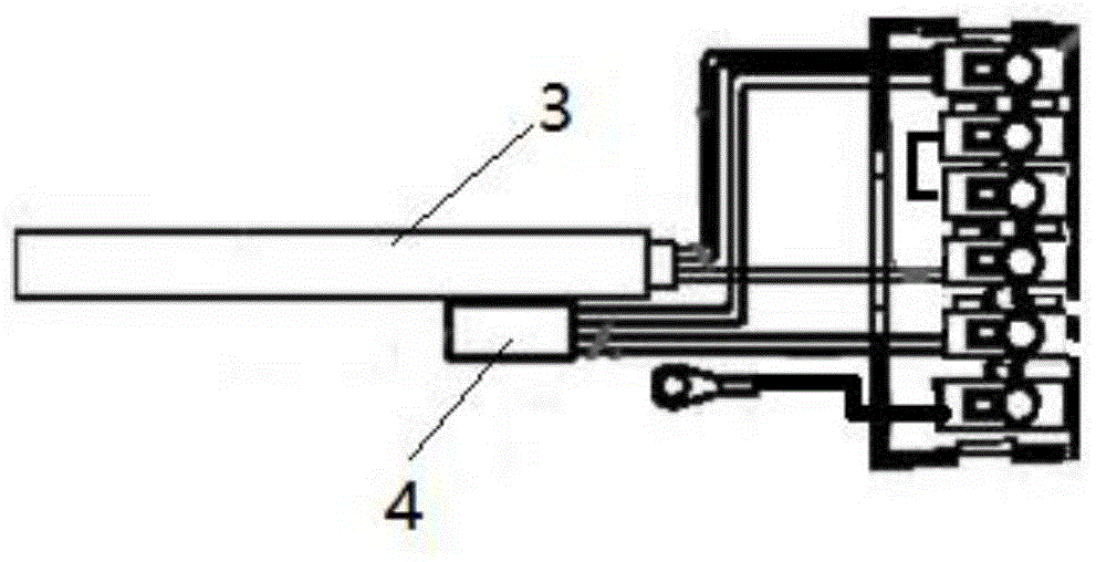
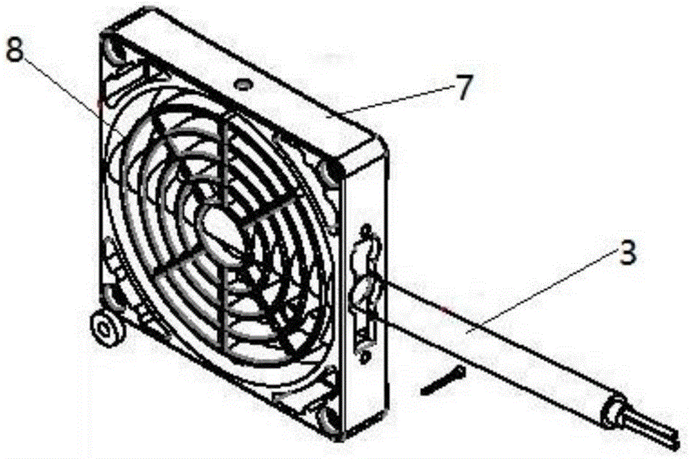
[0036] Such as figure 1 , figure 2 , image 3 and Figure 4 A compact fan heater shown includes: a housing 1, a fan 2, a heating tube 3, a thermostat 4, a power box 5 and a control device,

[0037] The housing 1 is composed of a front cover and a rear shell, the front cover and the rear shell are connected with the profile 7 by screws, the front cover is provided with a hand guard 8, the fan 2, the heating Both the tube 3 and the temperature controller 4 are located inside the housing 1, the power supply box 5 is located on one side of the housing 1, and the heating tube 3 and the temperature controller 4 are connected through the heating tube leads and the temperature controller respectively. The lead wire of the device is connected with the terminal 6 in the power supply box 5, and the control device is located in the power supply box 5, and the fan 2, the heating pipe 3 and the temperature controller 4 are all connected with the control device.

[0038] The fan 2 descr...

Embodiment 2

[0043] The structure of the fan heater in the working method of a compact fan heater described in this embodiment is the same as that in Embodiment 1.

[0044] A working method of a compact fan heater, the specific working method is as follows:

[0045] (1): First connect the heater to an external circuit;

[0046] (2): When the heater is connected to the external circuit, start to turn on the power to let it start to work;

[0047] (3): After the power is turned on, the heating tube 3 starts to work;

[0048] (4): The heating tube 3 will be continuously heated, and during the continuous heating process, the fan 2 is also continuously running;

[0049] (5): After the fan 2 works, it continuously dissipates the heat generated by the heater itself to ensure that it can work normally for a long time;

[0050] (6): During the above working process, once the temperature inside the heater reaches the maximum value preset by the thermostat (4), the thermostat 4 will automatically ...


PUM


Abstract

The invention discloses a compact fan heater. The compact fan heater comprises a shell, a fan, a heating pipe, a temperature controller, a power supply box and a control device, wherein the fan, the heating pipe and the temperature controller are all arranged in the shell; the control device is arranged in the power supply box; and the fan, the heating pipe and the temperature controller are all connected with the control device. The compact fan heater is additionally provided with the temperature controller; when the temperature in the heater is too high, the heater can be automatically cut off, and is stopped heating until the temperature in the heater is reduced, and the temperature controller is closed again to achieve a certain protection effect of the heater; the control device is used for realizing operation control of the whole heater; and the fan heater realizes intelligent and automatic operation.

Description

technical field [0001] The invention relates to a heater, in particular to a compact fan heater and a manufacturing process thereof. Background technique [0002] A heater is a device that can generate or produce high temperature. Generally speaking, the maximum temperature is about 70-300°C. It includes three parts: heat generation, heat dissipation and temperature control. Small household water heaters and large industrial boilers are actually derivatives of heaters, and heaters are just a general term for these products. There are thousands of different products and applications. It plays an important role in various fields. The heater is a kind of energy conversion equipment. The energy input into the heater is in the form of chemical energy in the fuel, electric energy, heat energy of high-temperature flue gas, etc. After being converted by the heater, the heat energy with a certain temperature is output to the outside, so that the Air or other substances are heated t...

Claims


Application Information

Patent Timeline
Patent Type & Authority Applications(China)
IPC IPC(8): F24D13/02F24D19/10
CPCF24D13/02F24D19/1096
Inventor 李睿曹祥记印晶晶
Owner BIHE ELECTRIC TAICANG CO LTD
Why Eureka
Try Eureka