A simple servo-controlled soil shear rheometer

A servo control and rheometer technology, applied in the field of geotechnical engineering, can solve problems such as difficult automatic storage, high cost, unstable applied stress, etc., to ensure displacement accuracy and motion stability, high precision, and stable shear stress level high degree of effect

Inactive Publication Date: 2017-05-10
CHINA UNIV OF GEOSCIENCES (WUHAN)
View PDF7 Cites 0 Cited by
  • Summary
  • Abstract
  • Description
  • Claims
  • Application Information

AI Technical Summary

Problems solved by technology

[0004] The existing rock and soil shear tester generally has the following characteristics: (1) the shear boxes are stacked vertically, and axial stress is applied in the vertical direction; (2) the lower half of the shear boxes is fixed, and The shear stress is applied to the upper shear box; (3) the deformation of the rock sample is usually read using a micrometer or a method of pasting a displacement strain gauge on the rock sample, but the subjective factors of the micrometer reading are too influential and cannot be carried out Automatic collection is not suitable for occasions with long creep time; while using displacement strain gauges, the test results are affected by too many interference factors, such as the position and distribution of strain gauges, and are affected by the defects of the rock sample itself. (4) Large-scale shearing instruments have disadvantages such as oil circuit voltage stabilization system and mechanical structure complex, expensive cost, etc., while some small shearing instruments have unstable applied stress, deformation data mostly rely on manual reading and are difficult to automatically store and other shortcomings

Method used


Image

  • A simple servo-controlled soil shear rheometer
  • A simple servo-controlled soil shear rheometer
  • A simple servo-controlled soil shear rheometer

Examples


Embodiment Construction

[0022] The present invention will be described in detail below in conjunction with the accompanying drawings and embodiments, and the content of the present invention is not limited to the following embodiments.

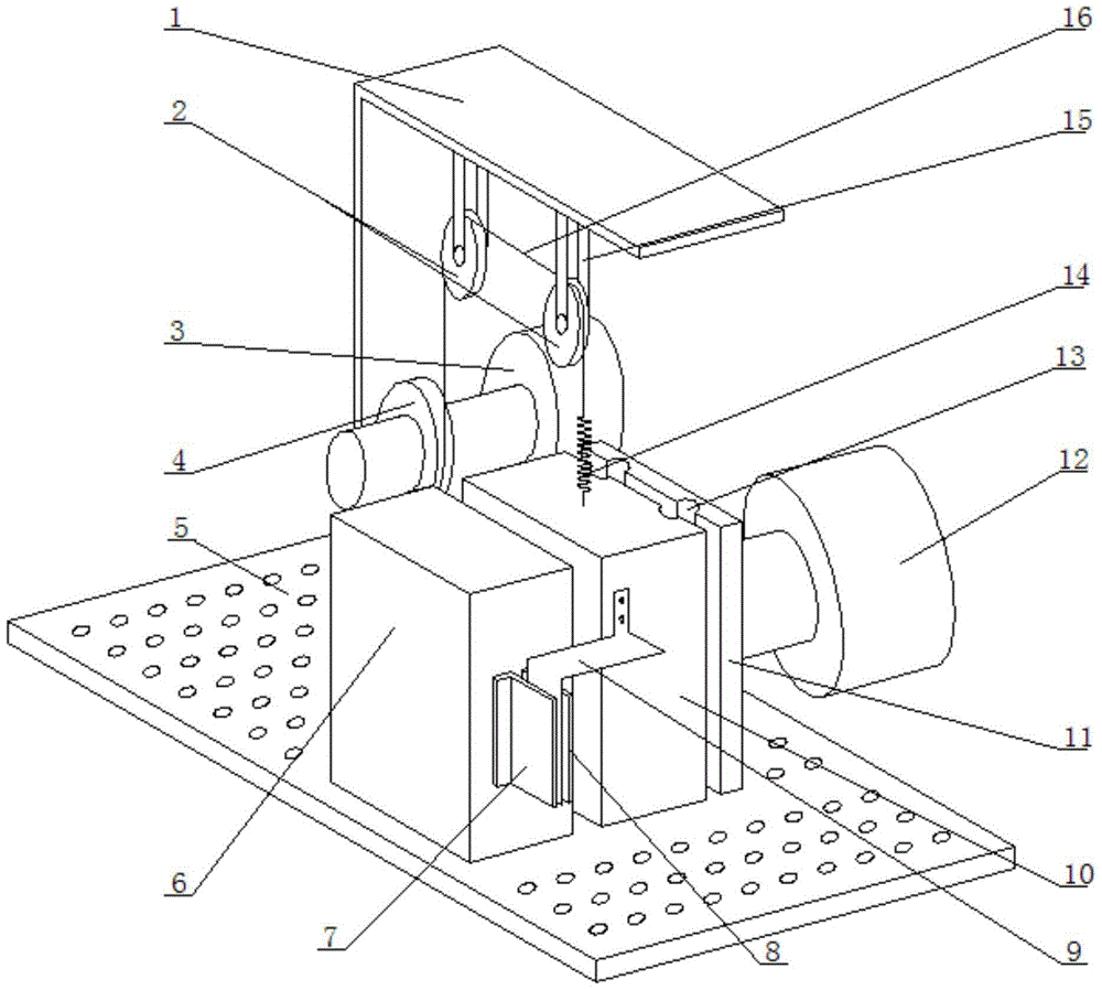
[0023] The simple servo-controlled soil shear rheometer provided by the present invention has a structure such as figure 1 As shown, it includes a base plate 5, a controller, a signal acquisition circuit, a displacement detection module, a shear box unit, a normal force loading device 12 and a shear force loading device, and the normal force loading device 12 is fixed on the base plate along the horizontal direction 5, the normal force loading device 12 is preferably a jack;

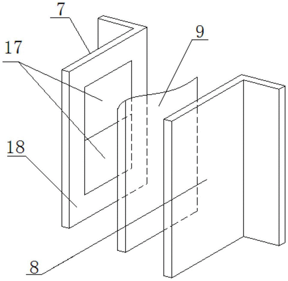
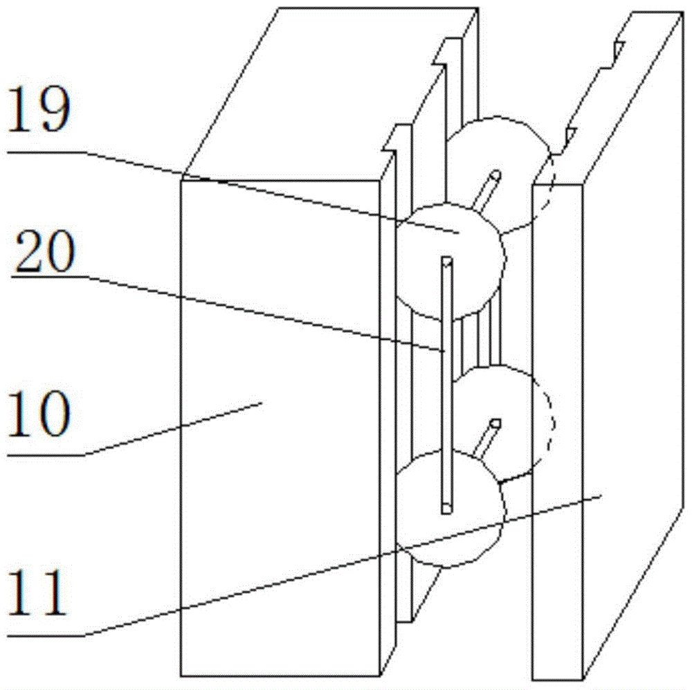
[0024] The shear box unit includes a front shear box 6, a rear shear box 10 and a dividing plate 11 that are installed in sequence along the horizontal direction and are all vertically placed. The front shear box 6 is fixed on the base plate 5 and is connected with the rear shear box. The open...


PUM


Abstract

The invention provides a simple servo controlled soil shearing rheometer. A shearing box unit comprises a front shearing box, a rear shearing box, and a partition plate; wherein the front shearing box, the rear shearing box, and the partition plate are installed in sequence along the horizontal direction and are all vertically placed. The front shearing box is fixed on a base plate, a normal force applying device is fixed on the base plate along the horizontal direction; the partition plate is fixed on the applying end of the normal force applying device and is tightly abutted on the rear shearing box; a shearing force applying device comprises a support, a motor, a lifting rope, a fixed pulley, and a spring; the support is fixed on the base plate, the fixed pulley is installed on the support, two ends of the lifting rope are connected to the rotation shaft of the motor and the spring respectively, the other end of the spring is fixed on the top part of the rear shearing box; a displacement detecting module is connected to the input terminal of a controller through a signal collecting circuit, the motor is connected to the output terminal of the controller; the shearing rheometer adopts a differential type infrared displacement sensor to measure the shearing displacement, the shear deformation measurement is precise therefore, the applied shearing force is stable, and the data can be collected automatically.

Description

technical field [0001] The invention relates to a soil shear rheometer, which belongs to the technical field of geotechnical engineering. Background technique [0002] Rheological properties are one of the important mechanical properties of rock and soil. Numerous engineering practices have shown that the instability and damage of geotechnical engineering does not occur at the beginning of use, but changes with time during the operation period. Accumulation, and then to the formation of major damage, resulting in project instability. Therefore, the study of the rheological properties of rock and soil has attracted more and more attention. Especially for rock and soil materials such as soil, soft rock, and weak interlayers, due to their own physical properties and structural characteristics, they have obvious creep effects. This creep effect plays a decisive role in the stability of geotechnical engineering such as high and steep mine slopes with weak interlayers, reservoir...

Claims


Application Information

Patent Timeline
Patent Type & Authority Patents(China)
IPC IPC(8): G01N3/24
CPCG01N3/24
Inventor 马冲胡斌詹红兵姚文敏
Owner CHINA UNIV OF GEOSCIENCES (WUHAN)
Why Eureka
Try Eureka