Scanning data correction method and system of two-dimensional scanning type laser radar
A technology of laser radar and scanning data, which is applied in the field of sensor detection to achieve the effect of overcoming errors
- Summary
- Abstract
- Description
- Claims
- Application Information
AI Technical Summary
Problems solved by technology
Method used
Image
Examples
Embodiment 1
[0086] like Image 6 As shown, the scanning data correction method of the two-dimensional scanning laser radar provided in this embodiment includes the following steps:
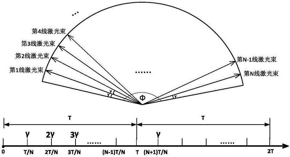
[0087] S1: Obtain the scanning parameters of the lidar, the scanning parameters shown include scanning period, angular resolution, scanning range, and line number;
[0088] S2: Obtain the distance information of the i-th laser beam within the scanning period;
[0089] S3: Obtain the current angle of the i-th line laser beam relative to the scanning environment according to the distance information of the i-th line laser beam and the distance of the line laser beam in the previous cycle;
[0090] S4: Obtain the current speed of the lidar through the sensor;
[0091] S5: Obtain the current distance from the i-th laser beam to the scanning environment according to the current speed;
[0092] S6: Obtain the correction value of the i-th line laser beam according to the current distance of the i-th line laser be...
Embodiment 2
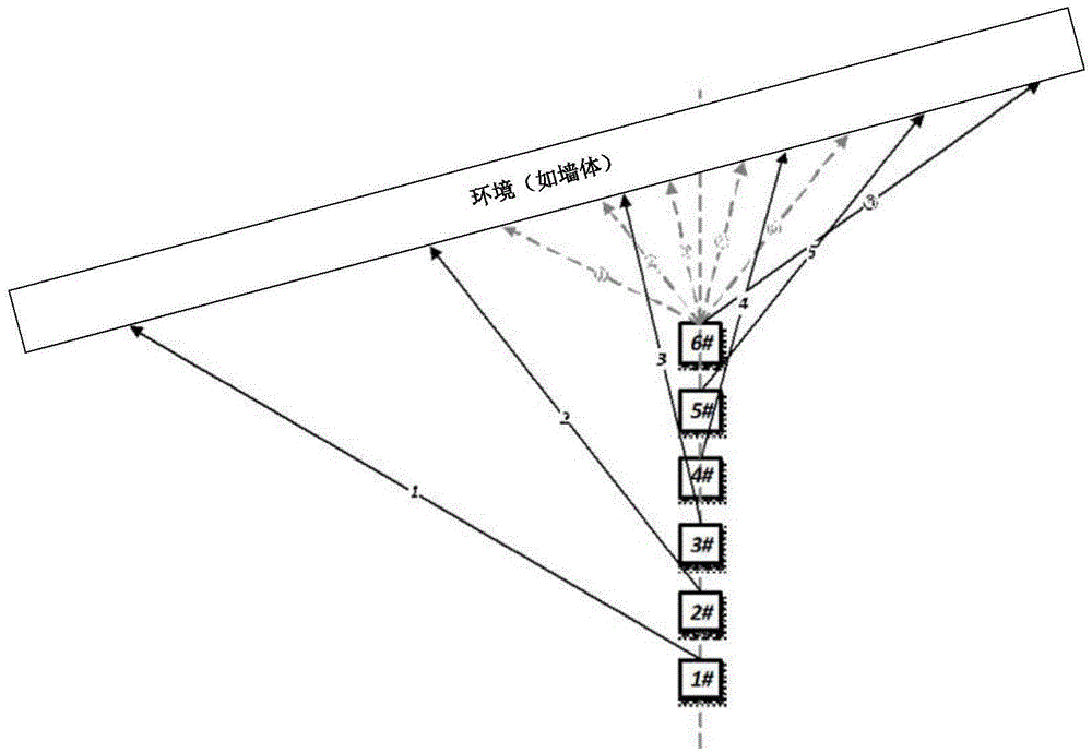
[0153] The error of the two-dimensional scanning laser radar is mainly determined by its scanning principle: the motor drives the rotating mirror to emit the laser beam. Within a detection cycle, there is a time difference between the detection start time and the detection end time. If the laser radar is in motion, then in this Spatial displacement will be accumulated in the time difference, thereby causing errors; in view of this problem, the scanning data correction method of the two-dimensional scanning laser radar provided in this embodiment obtains the attitude of the moving laser radar in real time, and in one laser radar scanning cycle The error calculation and compensation of the environmental data are carried out internally, so as to achieve the error correction of the scanning data of the two-dimensional scanning laser radar, so that when the robot moves relative to the environment, the accuracy of the environmental detection and the reliability of the robot are improv...
Embodiment 3
[0179] This embodiment will introduce the specific steps in detail:
[0180] Step 1: Rigidly connect the gyroscope or inertial navigation system to the lidar, and monitor the current speed of the lidar in real time through the sensor Get information from lidar and store the data of different lines.
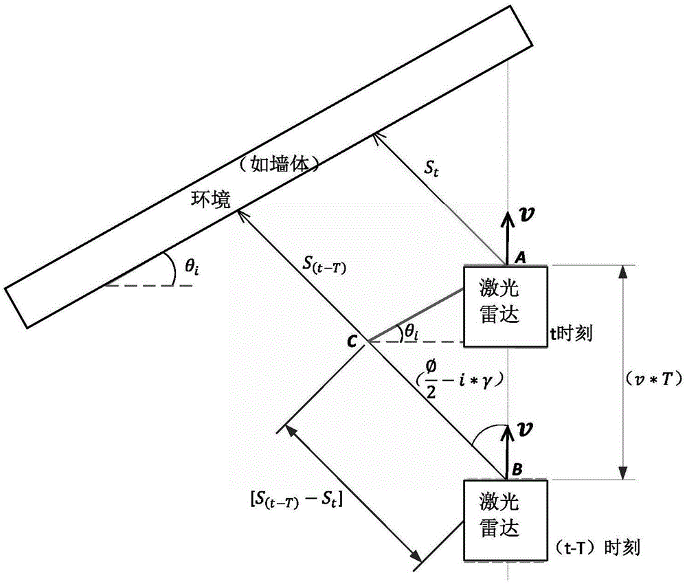
[0181] Step 2: Calculate the angle information of the environment (such as a wall) within the scanning range of the i-th laser beam.
[0182] (1) Read and store the scanning distance of the i-th line laser beam in the previous cycle as S (t-T) , read the scanning distance of the i-th line laser beam in the current period, set it as S t .
[0183] (2) pass figure 2 The geometric information of , the formula is derived as follows:
[0184]
[0185] therefore:
[0186]
[0187] and get:
[0188]
[0189] From this, the angle θ of the environment where the i-th laser beam scans is calculated i .
[0190] Step 3: Correct the i-th line lidar scanning data in the cu...
PUM
 Abstract
Description
Claims
Application Information
 - R&D
- Intellectual Property
- Life Sciences
- Materials
- Tech Scout
- Unparalleled Data Quality
- Higher Quality Content
- 60% Fewer Hallucinations
Browse by: Latest US Patents, China's latest patents, Technical Efficacy Thesaurus, Application Domain, Technology Topic, Popular Technical Reports.
© 2025 PatSnap. All rights reserved.Legal|Privacy policy|Modern Slavery Act Transparency Statement|Sitemap|About US| Contact US: help@patsnap.com


