Three-dimensional display device

A 3D display and 3D grating technology, applied in optics, instruments, optical components, etc., can solve problems such as moiré, crosstalk, and affecting the viewing effect of 3D display

Active Publication Date: 2016-05-11
BOE TECH GRP CO LTD
View PDF12 Cites 14 Cited by
  • Summary
  • Abstract
  • Description
  • Claims
  • Application Information

AI Technical Summary

Problems solved by technology

Using the existing 3D grating designed for ordinary pixels to realize naked-eye stereoscopic display, applied to the pixel

Method used


Image

  • Three-dimensional display device
  • Three-dimensional display device
  • Three-dimensional display device

Examples


example 1

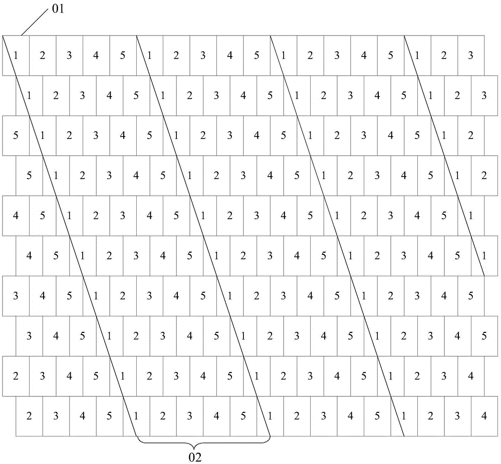
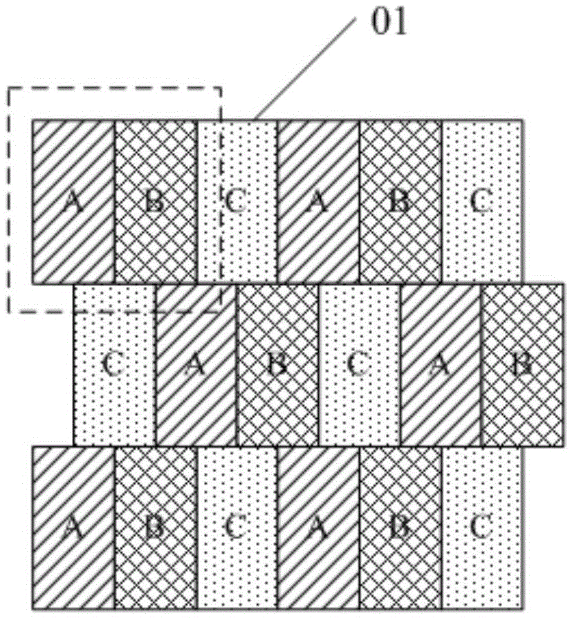
[0050] Example 1: When designing the edge of each strip grating structure 02, such as Figure 4 As shown, it is designed as an oblique line to divide each sub-pixel 01 overlapping with the edge into two parts, and the division ratio of each divided sub-pixel 01 is the same. That is, after each sub-pixel 01 overlapping with the edge is divided into two parts a and b, the shape of part a in each sub-pixel 01 is the same, and the shape of part b is also the same.

[0051] And, further, in order to reduce the crosstalk as much as possible, the area ratio of the two parts a and b divided into each sub-pixel 01 should be as large as possible. At this time, as Figure 4 As shown in , the edge of the oblique line should coincide with the vertices at the same position in the overlapping sub-pixels 01. Figure 4 The edge of the oblique line in the middle coincides with the upper left vertex of each overlapping sub-pixel 01 .

[0052] Further, in the above three-dimensional display dev...

example 2

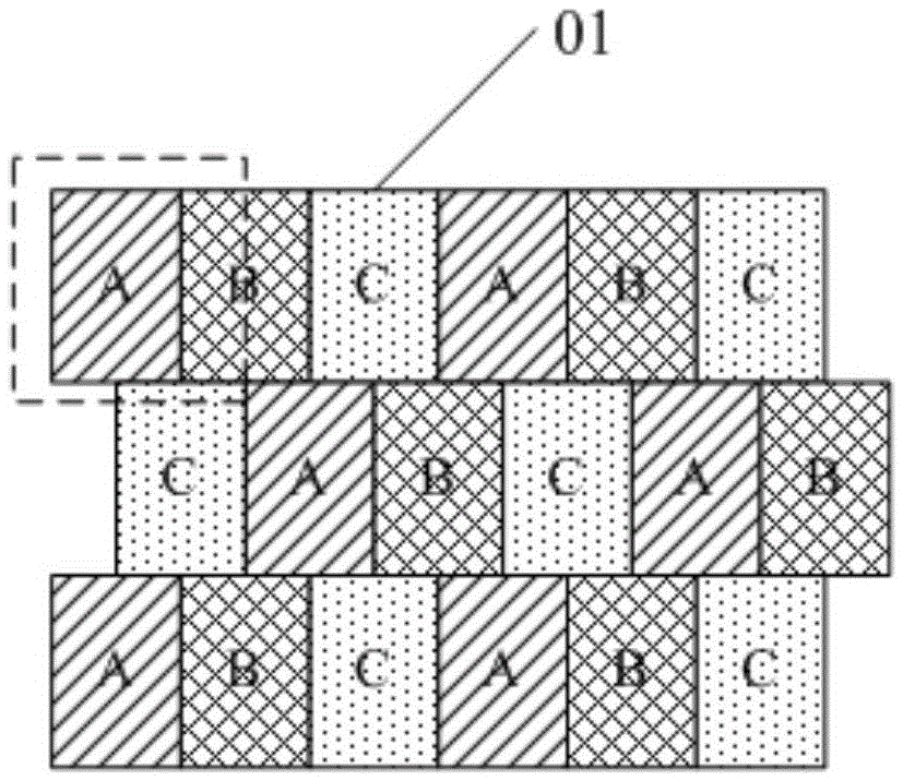
[0055] Example 2: When designing the edge of each strip grating structure 02, such as Figure 5 and Figure 6 As shown, it is designed as an oblique line to maximize the total division ratio of each sub-pixel 01 to be divided, that is, the sum of the parts a with a larger area and a smaller area are divided into each sub-pixel 01 that overlaps with the edge The greater the overall proportion of the sum of parts b, the better.

[0056] In specific implementation, it can be as Figure 5 As shown, the edge of the strip grating structure 02 is set on the line connecting the diagonal vertices of the two sub-pixels 01 aligned in the column direction at intervals of one row. At this time, when the aspect ratio of each sub-pixel 01 is 3:2, The inclination angle between the extension direction of the strip grating structure 02 and the horizontal direction is 77.47°. At this time, the viewpoint images displayed by each sub-pixel in the pixel structure take every 16 rows of sub-pixels...


PUM


Abstract

The invention discloses a three-dimensional display device. A plurality of closely arranged sub-pixels form a pixel structure, wherein the sub-pixels in each line of sub-pixels are arranged in an aligned manner. The sub-pixels in two adjacent lines of sub-pixels are staggered by one half sub-pixel in the row direction. The color of each sub-pixel is different from the colors of adjacent sub-pixels. A corresponding three-dimensional grating comprises a plurality of strip-shaped grating structures which are periodically arranged in the horizontal direction, wherein the extending direction of each strip-shaped grating structure is same and furthermore is at a certain inclination angle with the horizontal direction. At least two sub-pixels in the sub-pixels which correspond with each strip-shaped grating structure display different viewpoint images. The inclined strip-shaped grating structures are utilized for cooperating with the pixel structure in which the sub-pixels are staggered by one half sub-pixel in the row direction, and the proportion of the sub-pixels which are simultaneously covered by two adjacent strip-shaped grating structures can be reduced, thereby reducing crosstalk and Moire patterns in three-dimensional display, and improving view effect of three-dimensional display.

Description

technical field [0001] The present invention relates to the field of display technology, in particular to a three-dimensional display device. Background technique [0002] At present, the common pixel design of the display screen is RGB or RGBW design, that is, a pixel is composed of three sub-pixels or four sub-pixels for display, and its visual resolution is the physical resolution. However, with the increase of customers' requirements on display experience, panel manufacturers need to continuously increase the visual resolution (PPI) design of the display. At present, the physical resolution of the display screen is generally improved by reducing the pixel size. However, as the size of the pixels becomes smaller and smaller, the process of making the display becomes more and more difficult. [0003] In order to improve the visual resolution of the display, a technique of synthesizing two sub-pixels into one pixel, that is, a virtual display (Pentile) technique, has been...

Claims


Application Information

Patent Timeline
IPC IPC(8): G02B27/22G02B5/18G02B30/29G02B30/32
CPCG02B5/1866G02B30/27G02B30/29G02B30/32G02B5/18G02B27/022G02B27/0944G02B27/42
Inventor 吴坤
Owner BOE TECH GRP CO LTD
Why Eureka
Try Eureka