Foldable radar antenna framework and working method thereof
A radar antenna and antenna technology, which is applied to antennas, folded antennas, antenna parts and other directions, can solve the problems of prolonging the deployment time of radar systems, increasing installation/removal time, time-consuming and laborious installation, etc., to achieve convenient and quick adjustment accuracy and save time. and labor cost, the effect of smooth transmission
- Summary
- Abstract
- Description
- Claims
- Application Information
AI Technical Summary
Problems solved by technology
Method used
Image
Examples
specific Embodiment approach 1
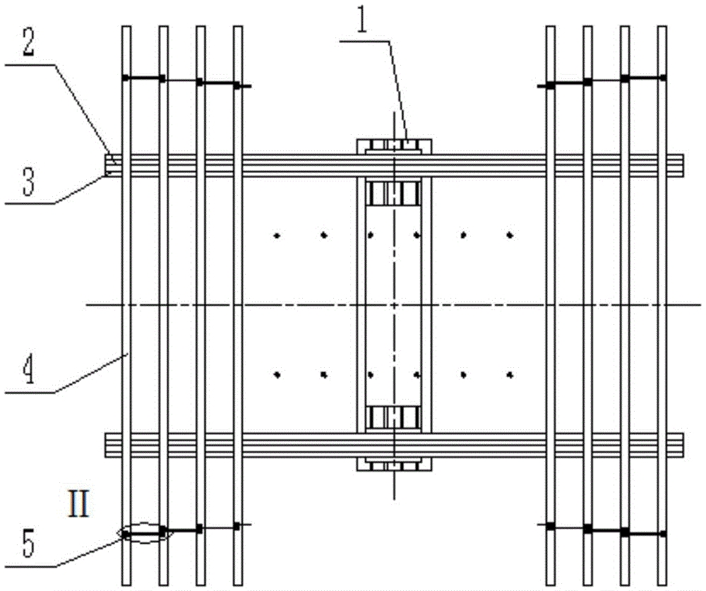
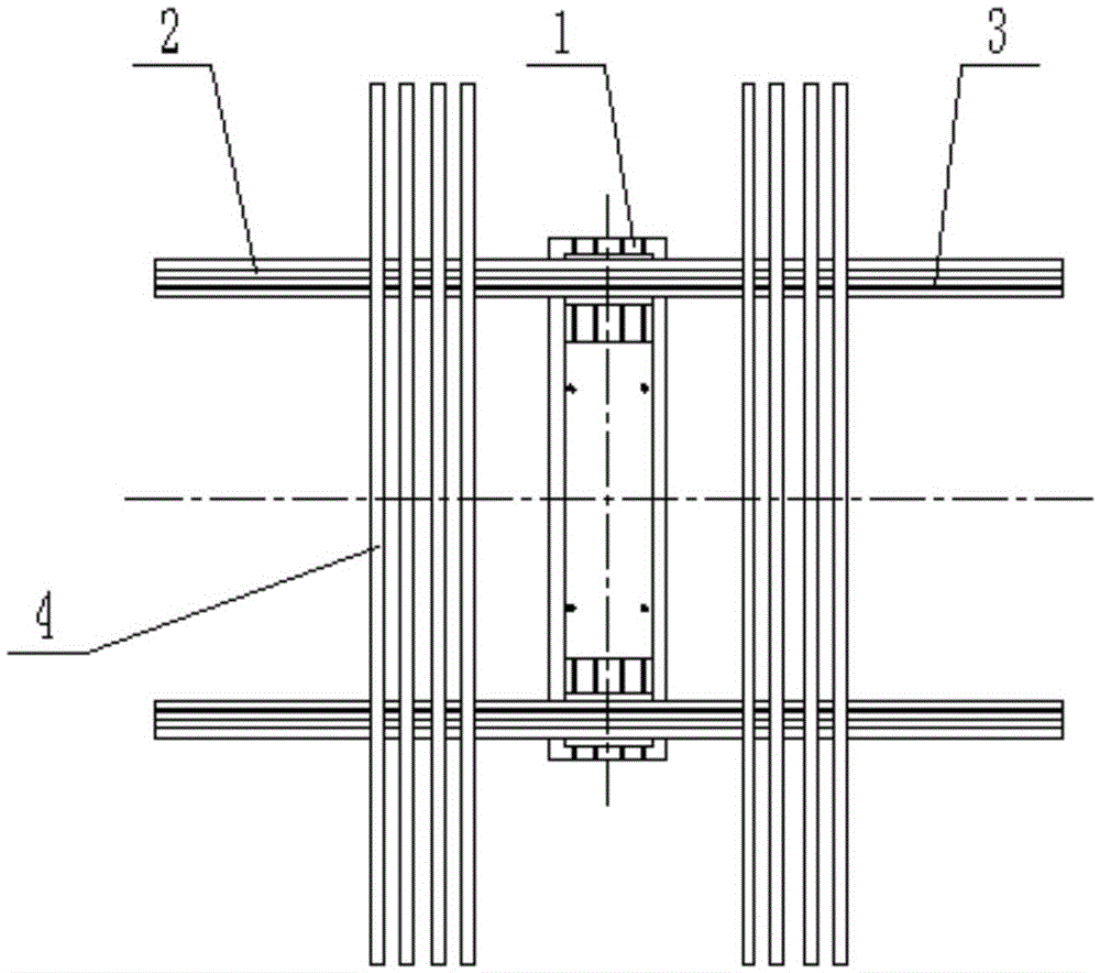
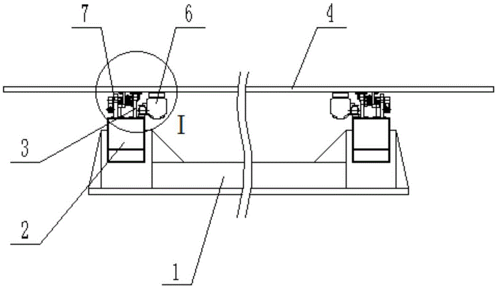
[0048] Combine below figure 1 , 2 , 3, 4, 5, 6, 7, 8, 9, 10, and 11 illustrate this embodiment. The present invention relates to the technical field of military vehicle-mounted radar, and more specifically, it is a foldable radar antenna framework, including a main support frame 1. Support arm 2, guide rail 3, antenna bearing rod 4, traction mechanism 5, driving mechanism 6 and locking mechanism 7.
[0049] The support arm 2 is arranged on the main support frame 1, and the support arm 2 is fixed on the main support frame 1 by welding or bolt connection, and any connection that can achieve fixation can be replaced. The guide rail 3 is fixedly connected to the support arm 2 by welding or bolts, and any connection that can achieve fixation can be replaced. The antenna bearing rod 4 is arranged above the support arm 2 , and the traction mechanism 5 is arranged on two adjacent antenna bearing rods 4 . The driving mechanism 6 is arranged between the guide rail 3 and the antenna b...
specific Embodiment approach 2
[0050] Combine below figure 1 , 2 , 3, 4, 5, 6, 7, 8, 9, 10, 11 illustrate this embodiment, the cross section of the guide rail 3 described in this embodiment is I-shaped, and the guide rail 3 is provided with an upper mating surface 3-1, Side matching surface 3-2, V-shaped matching surface 3-3, lower matching surface 3-4 and mounting surface 3-5. The upper mating surface 3-1 is located above the guide rail 3, the side mating surface 3-2 is located on the right side of the upper mating surface 3-1, the V-shaped mating surface 3-3 is opposite to the side mating surface 3-2, and the lower mating surface The surface 3-4 is opposite to the upper mating surface 3-1. The installation surface 3 - 5 is located below the guide rail 3 .
specific Embodiment approach 3
[0051] Combine below figure 1 , 2 , 3, 4, 5, 6, 7, 8, 9, 10, 11 illustrate this embodiment, the driving mechanism 6 described in this embodiment includes a motor reducer 6-1, a gear 6-2, and a rack 6-3 , the front guide wheel 6-4 and the side guide wheel group 6-5, the motor reducer 6-1 is installed on the lower surface of the antenna bearing rod 4, and the gear 6-2 is installed on the output of the motor reducer 6-1 On the shaft, the rack 6-3 is fixedly connected to the upper surface of the guide rail 3, and the front guide wheel 6-4 and the side guide wheel set 6-5 are all installed on the lower surface of the antenna bearing rod 4. Described gear 6-2 is meshed with rack 6-3. The front guide wheel 6-4 matches the upper mating surface 3-1 of the guide rail 3, the front guide wheel 6-4 has a flange, and the flange of the front guide wheel 6-4 matches the side of the guide rail 3. The mating surfaces 3-2 are matched. Described side guide wheel group 6-5 comprises two groups...
PUM
 Abstract
Description
Claims
Application Information
 - R&D
- Intellectual Property
- Life Sciences
- Materials
- Tech Scout
- Unparalleled Data Quality
- Higher Quality Content
- 60% Fewer Hallucinations
Browse by: Latest US Patents, China's latest patents, Technical Efficacy Thesaurus, Application Domain, Technology Topic, Popular Technical Reports.
© 2025 PatSnap. All rights reserved.Legal|Privacy policy|Modern Slavery Act Transparency Statement|Sitemap|About US| Contact US: help@patsnap.com


