Eureka AIR delivers breakthrough ideas for toughest innovation challenges, trusted by R&D personnel around the world.

Frame-type power supply track and track equipment based on the power supply track

A power supply rail and frame type technology, applied in transformer/inductor parts, circuits, electrical components, etc., can solve problems such as poor system operation performance, and achieve the effects of small magnetic field leakage, low manufacturing cost, and low construction difficulty

Active Publication Date: 2018-09-07
HARBIN INST OF TECH
View PDF2 Cites 0 Cited by
  • Summary
  • Abstract
  • Description
  • Claims
  • Application Information

AI Technical Summary

Problems solved by technology

At present, in the system that realizes wireless power supply for mobile transportation equipment, the system performance is poor, so how to design and develop a wireless power supply system for mobile transportation equipment with high system performance is very necessary

Method used


Image

  • Frame-type power supply track and track equipment based on the power supply track
  • Frame-type power supply track and track equipment based on the power supply track
  • Frame-type power supply track and track equipment based on the power supply track

Examples


specific Embodiment approach 1

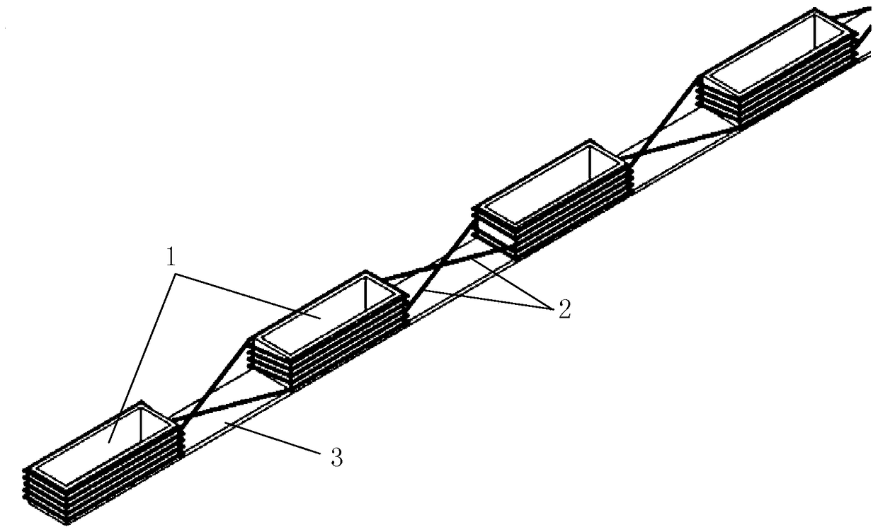
[0023] Specific implementation mode one, reference Figure 1 to Figure 4 To describe this embodiment in detail, the frame-shaped power supply rail for wireless power supply for mobile transportation equipment described in this embodiment includes n magnetic poles 1, power supply cables 2 and magnetic cores 3, 2≤n, and n is an integer;

[0024] The n magnetic poles 1 are all hollow rectangular frame structures; the magnetic core 3 is a flat magnetic core; the bottom width of the magnetic pole 1 is equal to the width of the magnetic core 3; the bottom of the n magnetic poles 1 are all fixed on the magnetic core 3;

[0025] The power supply cable 2 is wound along the outer surface of the magnetic pole 1, from bottom to top along the outer surface of the first magnetic pole 1 to the middle position of the first magnetic pole 1, and then continues to wind along the outer surface of the second magnetic pole 1 from bottom to top To the middle position of the second magnetic pole 1, and so...

specific Embodiment approach 2

[0027] Specific implementation mode two, reference Figure 5 To describe this embodiment in detail, the frame-shaped power supply rail for wireless power supply for mobile transportation equipment described in this embodiment includes n magnetic poles 1, power supply cables 2 and magnetic cores 3, 2≤n, and n is an integer;

[0028] The n magnetic poles 1 are all hollow rectangular frame structures; the magnetic core 3 is a flat magnetic core; the bottom width of the magnetic pole 1 is equal to the width of the magnetic core 3; the bottom of the n magnetic poles 1 are all fixed on the magnetic core 3;

[0029] The power supply cable 2 is wound along the outer surface of the magnetic pole 1, and first wound along the same height as the first magnetic pole, the second magnetic pole,..., the n-1th magnetic pole, and the nth magnetic pole outer surface. The winding method is cross-winding along one side of the first magnetic pole, the other side of the second magnetic pole,..., one side ...

specific Embodiment approach 3

[0035] Embodiment 3: This embodiment is a further description of the frame-shaped power supply track applied to the wireless power supply of mobile transportation equipment described in Embodiment 1 or 2. In this embodiment, the magnetic pole 1 is a ferrite pole.


PUM


Abstract

The invention provides a box-type power supply rail applied to wireless power supply of mobile transportation equipment and power supply rail-based rail equipment, belongs to the technical field of magnetic coupling resonant wireless power transmission, and achieves the target of improving the performance of a system in achievement of wireless power supply for the mobile transportation equipment. The bottom parts of n magnetic poles all are fixed on a magnetic core; a power supply cable is wound along the outer surfaces of the magnetic poles, is wound to the middle position of the first magnetic pole from bottom to top along the outer surface of the first magnetic pole, further wound to the middle position of the second magnetic pole from bottom to top along the outer surface of the second magnetic pole, and so on; the power supply cable is wound to the top end of the nth magnetic pole from bottom to top along the outer surface of the nth magnetic pole, returns to the middle position of the outer surface of the (n-1)th magnetic pole to be wound to the bottom end from top to bottom until the power supply cable is wound on the outer surfaces of all magnetic poles; and the winding modes of the power supply cables on two adjacent magnetic poles are opposite. The box-type power supply rail is suitable for wireless power supply of electric vehicles.

Description

Technical field [0001] The invention belongs to the technical field of magnetic coupling resonance type wireless power transmission. Background technique [0002] With the increasing awareness of low-carbon environmental protection and green energy conservation, more and more mobile transportation equipment uses electric energy as their power source. Common power supply methods include sliding contact, cable drag chain and battery-powered. Among them, the sliding contact method has low safety and reliability and high maintenance cost. The cable drag chain type has strict restrictions on the moving distance, and the use environment is very limited. In occasions that require high equipment flexibility, battery power is usually used. There are two shortcomings of battery power supply. One is the size, weight, price, material, safety, charging speed, and life of the battery. The production process of the battery is highly polluting, consuming resources, and destroying the ecological...

Claims


Application Information

Patent Timeline
Patent Type & Authority Patents(China)
IPC IPC(8): H02J50/12H01F27/30
CPCH01F27/306
Inventor 朱春波魏国汪超姜金海
Owner HARBIN INST OF TECH
Why Eureka
Eureka Blog
Learn More