Excavator steering drive axle

A technology for steering drive axles and excavators, applied in the directions of axles, wheels, control devices, etc., can solve the problem of reducing the transmission torque and service life of the planetary reduction mechanism, dislocation meshing of the sun gear and planetary gear sets on different axes, affecting the planetary reduction mechanism. Service life and other issues, to achieve the effect of increasing output torque, reducing assembly process requirements, and improving service life

Inactive Publication Date: 2016-05-18
QUANZHOU KINHO CONSTR MACHINERY TECH
View PDF5 Cites 7 Cited by
  • Summary
  • Abstract
  • Description
  • Claims
  • Application Information

AI Technical Summary

Problems solved by technology

When the driving front axle is actually used, the precision of the coaxial surface engagement between each planetary gear set and the sun gear is very high. Rigid positioning, when the vehicle is running, the wheel hub will move up, down, left, and right. Long-term use will affect the positioning of the planetary reduction mechanism, and it is prone to misalignment and meshing between the sun gear and the planetary gear sets, thereby reducing the planetary reduction. The transmission torque and service life of the mechanism, and the axial steel contact and impact between the wheel-side planetary reduction mechanism and the output end of the universal transmission torque will also affect the service life of the planetary reduction mechanism and the universal transmission mechanism. generates noise

Method used


Image

  • Excavator steering drive axle
  • Excavator steering drive axle
  • Excavator steering drive axle

Examples


Embodiment Construction

[0017] The present invention will be further described below in conjunction with the accompanying drawings and specific embodiments.

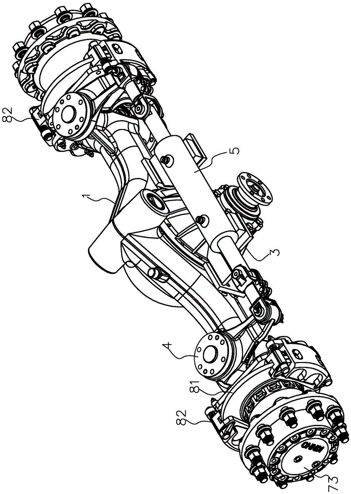
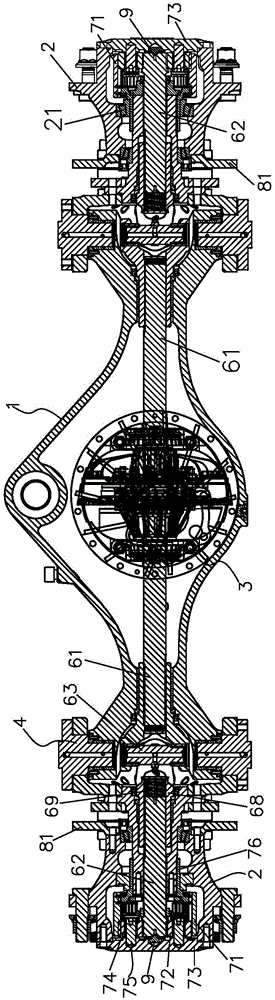
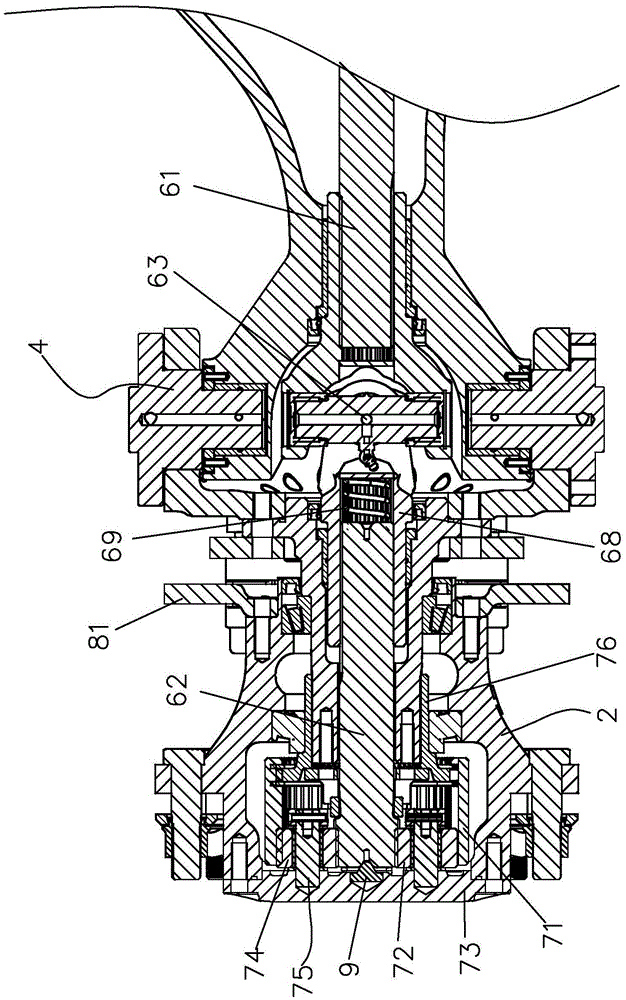
[0018] Such as Figure 1 to Figure 4 , the present invention discloses an excavator steering drive axle, comprising an axle housing 1, two braking devices, two hubs 2, a transmission device and a steering device, the axle housing 1 is approximately axially extending and has a hollow structure, and the transmission The device includes two parts, the final drive 3 (including the differential) and the universal drive. The final drive 3 is located in the middle of the inner side of the axle housing 1 to convert the radial torque input of the engine into an axial torque output. The devices are respectively installed on the hubs 2 at both ends of the axle housing 1 to control the rotation of the hubs 2. The two hubs 2 are rotatably installed at both ends of the axle housing 1 through bearings 21. The axial torque of the reducer 3 is respectively out...


PUM


Abstract

The invention relates to a vehicle walking device and provides an excavator steering drive axle having axial compensation positioning and flexible axial limiting effects. The excavator steering drive axle comprises an axle housing, two brake devices, two hubs, a transmission and a steering apparatus, wherein the axle housing axially extends and is of hollow structure, the transmission comprises a main speed reducer and universal drives, the main speed reducer is arranged in the middle of the inner side of the axle housing and used for inputting and converting a radial torque of an engine into an axial torque to be output, the two brake devices are respectively arranged on the hubs at two ends of the axle housing and used for controlling drive of the hubs, the two hubs are respectively and rotatably arranged at two ends of the axle housing, and the universal drives are arranged in a steering knuckle and output and transfer the axial torque of the main speed reducer to the two hubs rotating with respect to the brake devices respectively. The steering apparatus is arranged between the axle housing and the two hubs and controls rotating angles of the two hubs through the steering knuckle to achieve steering of an automobile, a wheel side planetary speed reducing mechanism is arranged between the torque output end of the universal drives and the two hubs respectively, the axial torque output ends of the universal drives are respectively provided with a flexible axial compensation limiting device enabling all sun wheels and all planetary gears on the planetary speed reducing mechanisms to be always kept meshed and driven on the same axial face.

Description

technical field [0001] The invention relates to a vehicle traveling device, in particular to an excavator steering drive axle. Background technique [0002] Excavator steering drive front axle is known, including axle housing, two braking devices, two hubs, transmission device and steering device, the axle housing is generally axially extending and hollow structure, transmission device includes final drive (including the differential) and the universal transmission. The main reducer is set in the middle of the inner side of the axle housing to convert the radial torque input of the engine into the axial torque output. Two braking devices are respectively installed at both ends of the axle housing. Inside the hub, two hubs are rotatably arranged at both ends of the axle housing respectively, and the universal drive is arranged in the steering knuckle to transmit the axial torque output of the final reducer to the hub that can rotate relative to the braking device. It is loca...

Claims


Application Information

Patent Timeline
Patent Type & Authority Applications(China)
IPC IPC(8): B60K17/08B60B35/14
CPCB60K17/08B60B35/14
Inventor 谢帮亮林秀丹林文捷
Owner QUANZHOU KINHO CONSTR MACHINERY TECH
Why Eureka
Try Eureka