Motor driven transfer case with modular actuation

A gearbox and actuation technology, applied in the direction of vehicle gearbox, transmission, transmission control, etc., can solve problems such as complex gearbox

Active Publication Date: 2016-05-18
BORGWARNER INC
View PDF15 Cites 8 Cited by
  • Summary
  • Abstract
  • Description
  • Claims
  • Application Information

AI Technical Summary

Problems solved by technology

Specifically, worm gear drives, cams, barrel cams, gear reducers, shift shafts, shift forks, etc. ...

Method used


Image

  • Motor driven transfer case with modular actuation
  • Motor driven transfer case with modular actuation
  • Motor driven transfer case with modular actuation

Examples


Embodiment Construction

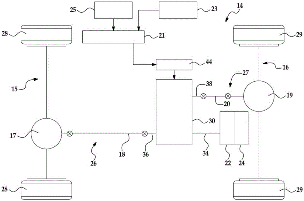
[0016] now refer to figure 1 , the vehicle 14 may include an internal combustion engine 24 and a power transfer device 22 for generating and transmitting drive torque to a front powertrain 26 and a rear powertrain 27 . The vehicle 14 may further include a transmission 30 that transmits drive torque from the internal combustion engine 24 and the power transfer device 22 to the front driveline 26 and the rear driveline 27 . Front driveline 26 may include a pair of front wheels 28 coupled to distally opposite ends of front axle assembly 15 , including front differential 17 , which may be coupled to front drive shaft 18 . An opposite end of the front powertrain 18 can be coupled to a first output shaft 36 of a transmission 30 . The first output shaft 36 can drive the front drive shaft 18 , and the front differential 17 can transmit driving energy to the pair of front wheels 28 through the front axle assembly 15 . Rear driveline 27 may include a pair of rear wheels 29 coupled to ...


PUM


Abstract

A transfer case (30) and a method of assembly in an all-wheel drive vehicle can include a range shifting assembly (60) for shifting between a low-range and high-range drive mode, a normally disengaged clutch assembly (80) for transferring drive torque to a first and second driveline, a clutch actuator (88), and an actuating gear (48). The clutch actuator (88) can be moveable between an expanded position and a contracted position and engageable with the clutch assembly (80) for engaging the clutch assembly (80) when in the expanded position. The actuating gear (48) can be reversibly rotatable through a predetermined angular arc of movement for operating the clutch actuator (88) between the contracted and expanded position for actuating the clutch assembly (80) and for shifting the range shifting assembly (60) between a low-range drive mode and a high-range mode when the clutch assembly (80) is in the disengaged position.

Description

field of invention [0001] The present invention relates to a joint control mechanism of a transmission and a clutch or a brake, in particular to a mechanism for fixing and releasing the drive continuity between two shafts or between a pulley and a shaft or between other driving parts and driven parts by using friction or interlocking parts A power transmission device including an actuating device for switching the power transmission device into or out of a state in which the power transmission device provides continuity of drive between the driving member and the driven member. Background technique [0002] Transmissions are used in vehicle powertrain applications to selectively transfer drive torque from the powertrain to the wheels of a four-wheel drive or two-wheel drive vehicle. Transmissions have been previously described in U.S. Patent No. 7,650,808; U.S. Patent No. 6,945,375; U.S. Patent No. 6,814,682; U.S. Patent No. 6,808,053; Published in Application No. 2003 / 0224...

Claims


Application Information

Patent Timeline
IPC IPC(8): F16H37/08F16H61/26
CPCF16H37/08F16H61/26F16H2702/02B60K2023/0858F16H63/304B60K17/344F16H2063/3056F16H61/32F16H63/32F16H59/08F16H2061/2869F16H2061/326
Inventor L·A·普里查德D·E·扬J·马斯迪D·尼费尼格C·库马尼亚克
Owner BORGWARNER INC
Why Eureka
Try Eureka