Precision ball reducer

A technology of reducer and deceleration equipment, which is applied in the direction of mechanical equipment, belt/chain/gear, transmission device, etc. It can solve the problems of small number of teeth, low power conversion efficiency, and large friction coefficient, so as to improve output torque and power High conversion efficiency and low friction

Inactive Publication Date: 2016-05-18
吴泽胜
View PDF0 Cites 0 Cited by
  • Summary
  • Abstract
  • Description
  • Claims
  • Application Information

AI Technical Summary

Problems solved by technology

[0003] 1. There is hysteresis (backlash) in the product, which directly affects the control accuracy
[0004] 2. Multi-processing and assembly of accessories is difficult
[0005] 3. If you want to improve the accuracy level, the investment in equipment is large
[0006] 4. The friction coefficient is large and the power conversion efficiency is low.
[0007] 4. The number of teeth meshes is small, and the force on a single tooth is high, and it is easy to break
[0008] 5. After the tooth surface is worn out, the possibility of zero parts repairing to high precision is zero
[0009] 6. Due to the existence of hysteresis, the accuracy of multi-stage large speed ratio is even lower, and the output accuracy error is superimposed

Method used


Image

  • Precision ball reducer
  • Precision ball reducer
  • Precision ball reducer

Examples


Embodiment 1)

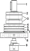
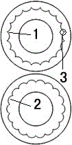
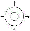
[0018] The motor drives the input shaft 9 to rotate, and the input shaft 9 is designed with a dynamic balance structure. The eccentric part (eccentric value p) in the middle of the input shaft 1 drives the fluctuation disc 5 to rotate. Bearing connection, when the input shaft 1 rotates, the wave plate produces two movements, one motion is to follow the circular rotation of the input shaft, and the other motion is to fluctuate with the eccentric part of the input shaft, and the anti-rotation plate 6 restricts the circular rotation of the wave plate 5 , let the fluctuation plate 5 do translational cross fluctuation according to the eccentric value p (see image 3 ). At this time, any point on the fluctuation plate 5 (take point D) will have the harmonic generated by the superposition of the point D's own position and translation fluctuation (see figure 2 Middle 1), assuming that the ball is fixed above the point D, according to the relative movement, the ball can walk out a ha...


PUM


Abstract

The invention discloses a precision ball reducer. Gears are replaced by precision balls, all the precision balls are made to do differential gear movement in two pre-machined harmonic grooves, and therefore precision speed changing is generated. According to the precision ball reducer, the output accuracy of the reducer is increased to zero back clearance, meanwhile, the accuracy of a multi-stage large-speed-ratio reducer is improved, the friction coefficient is lowered, output torque is increased, and machining equipment cost is lowered.

Description

technical field [0001] The invention belongs to the field of precision reducer equipment, and relates to a new method for realizing high-precision deceleration technology at low cost. Background technique [0002] At present, the known reducer has some problems in product production due to the influence of gear processing equipment accuracy, various parts processing accuracy, assembly accuracy, heat treatment process, and gear materials, specifically: [0003] 1. There is hysteresis (backlash) in the product, which directly affects the control accuracy. [0004] 2. It is difficult to process and assemble more accessories. [0005] 3. If you want to improve the accuracy level, the investment in equipment is large. [0006] 4. Large friction coefficient and low power conversion efficiency.. [0007] 4. The number of teeth meshes is small, and the force on a single tooth is high, and it is easy to break. [0008] 5. After the tooth surface is worn, the possibility of ...

Claims


Application Information

Patent Timeline
Patent Type & Authority Applications(China)
IPC IPC(8): F16H49/00
CPCF16H49/001
Inventor 吴泽胜
Owner 吴泽胜
Why Eureka
Try Eureka