Joint calibration method of binocular camera and inertial navigation unit in automatic driving

A technology of inertial navigation and binocular camera, which is applied in the field of joint calibration of binocular camera and inertial navigation unit in automatic driving, can solve problems such as camera data errors, and achieve rapid calibration, simple tools and processes

Active Publication Date: 2016-05-18
WUHAN KOTEI TECH CORP
View PDF4 Cites 69 Cited by
  • Summary
  • Abstract
  • Description
  • Claims
  • Application Information

AI Technical Summary

Problems solved by technology

[0003] However, in actual use, the data information obtained by the camera refers to the camera's own coordinate system, so there are high requirements for the camera installation angle and the stability of the carrier attitude, especially in the fields of high-precision surveying and mapping and unmanned driving. Changes in the attitude of the car during driving will cause obvious errors in the camera data

Method used


Image

  • Joint calibration method of binocular camera and inertial navigation unit in automatic driving
  • Joint calibration method of binocular camera and inertial navigation unit in automatic driving
  • Joint calibration method of binocular camera and inertial navigation unit in automatic driving

Examples


Embodiment Construction

[0031] The present invention will be further described below in conjunction with the accompanying drawings and embodiments.

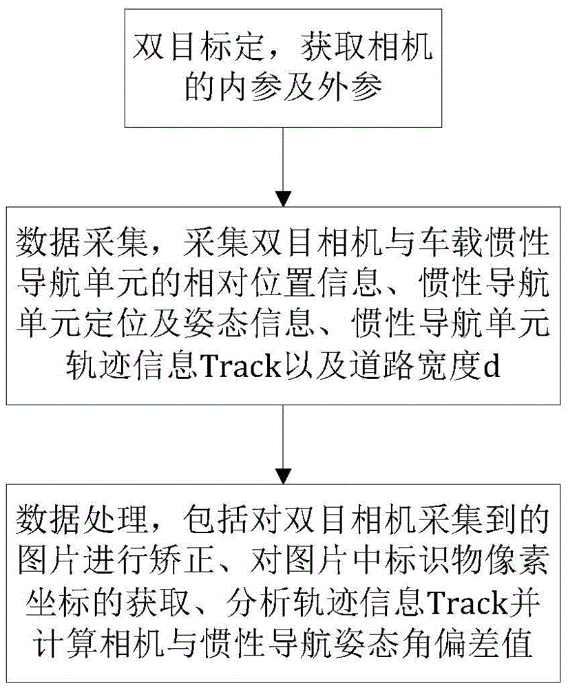
[0032] An embodiment of the present invention provides a method for joint calibration of a binocular camera and an inertial navigation unit in automatic driving, including the following steps:

[0033] 1: Preparation stage

[0034] ①Two-target positioning, to obtain the internal and external parameters of the camera;

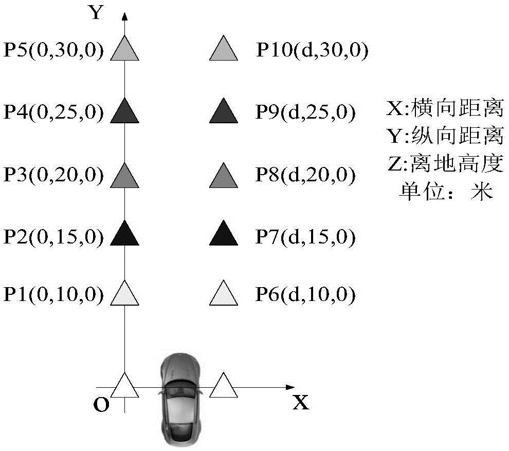
[0035] 2: Data collection

[0036] ①Measure the three-dimensional offset (ΔTx, ΔTy, ΔTz) of the left eye camera relative to the antenna after the integrated inertial navigation and the height h of the binocular camera from the ground with measuring tools such as a tape measure or tape measure, accurate to centimeters; since the binocular parameters have already It includes the spatial position relationship of the left and right cameras, so it is only necessary to calibrate the left or right camera and the inertial navigation to determin...


PUM


Abstract

The invention provides a joint calibration method of a binocular camera and an inertial navigation unit in automatic driving. The joint calibration method comprises steps as follows: acquisition of internal parameters and external parameters of the binocular camera; data acquisition: relative position information of the binocular camera and the vehicle-mounted inertial navigation unit, positioning and altitude information of the inertial navigation unit, track information Track of an inertial navigation module and the road width d are acquired; data processing: pictures acquired by the binocular camera are corrected, pixel coordinates of markers in the pictures are acquired, the track information Track is analyzed, the deviation value of the camera and an inertial navigation altitude angle is calculated, the spatial position relation of the binocular camera relative to the inertial navigation unit is acquired in a calibration manner, and influence of the altitude of the camera on road image data acquisition can be effectively compensated.

Description

technical field [0001] The invention relates to the technical field of unmanned vehicles, in particular to a method for joint calibration of a binocular camera and an inertial navigation unit in automatic driving. Background technique [0002] With the rapid development of digital image processing technology and artificial automation, cameras, as comprehensive and low-cost sensors, have received more and more attention and applications in the fields of map mapping and automatic vehicles. Among them, monocular applications include: lane line detection, forward collision warning, traffic sign detection, etc.; binocular applications include: object ranging, 3D scene reconstruction, etc. [0003] However, in actual use, the data information obtained by the camera refers to the camera's own coordinate system, so there are high requirements for the camera installation angle and the stability of the carrier attitude, especially in the fields of high-precision surveying and mapping ...

Claims


Application Information

Patent Timeline
Patent Type & Authority Applications(China)
IPC IPC(8): G01C21/16G06T7/00
CPCG01C21/165
Inventor 苏晓聪辛梓朱敦尧
Owner WUHAN KOTEI TECH CORP
Why Eureka
Try Eureka