A low-speed wind tunnel model powered flight test power system

A power system and flight experiment technology, applied in aerodynamic tests, measuring devices, instruments, etc., can solve the problems of aircraft model design difficulties, low engine power density, and inability to install aircraft models, etc., and achieve good engineering application prospects, Low frictional resistance and light weight

Inactive Publication Date: 2017-09-29
LOW SPEED AERODYNAMIC INST OF CHINESE AERODYNAMIC RES & DEV CENT
View PDF4 Cites 0 Cited by
  • Summary
  • Abstract
  • Description
  • Claims
  • Application Information

AI Technical Summary

Problems solved by technology

[0003] In the prior art, there are generally the following three methods for providing similar power for aircraft models: (1) electric ducted fan motors. It is difficult; and the power density of this engine is small, and it needs a large engine to provide sufficient thrust, which cannot be installed in the aircraft model; in addition, this method also has the problem of short service life of the bearings
(2) Small turbojet engine, this kind of engine also needs to provide unobstructed air flow passage for the aircraft model; because of its own structure, the general volume limits the required installation space, and it cannot be installed in the model; there are also bearings used Shorter life; and the need to solve the model protection and personnel protection problems generated by high temperature gas
(3) High-pressure turbine power simulator (TPS simulator). The TPS simulator can simulate the thrust and impact of the engine to the greatest extent, but its system is complex, requires more auxiliary systems, and is expensive; and the driving pressure is high. Practical metal high-pressure pipelines are required, which limits the free movement of the aircraft model in the wind tunnel; the service life of the bearings is only about 100 hours

Method used


Image

  • A low-speed wind tunnel model powered flight test power system
  • A low-speed wind tunnel model powered flight test power system
  • A low-speed wind tunnel model powered flight test power system

Examples


Embodiment Construction

[0028] In order to make the purpose, technical solution and advantages of the present invention clearer, the present invention will be further elaborated below in conjunction with the accompanying drawings.

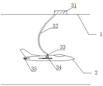
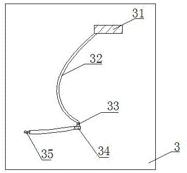
[0029] In Example 1, see figure 1 and figure 2 As shown, the present invention proposes a low-speed wind tunnel model driving force flight test power system, including a wind tunnel test section 1, an aircraft model 2 and a power system 3, and the power system 3 includes a needle valve 31, a high-pressure hose 32, Swivel joint 33, resident chamber 34 and nozzle pipe 35; the needle valve 31 is arranged outside the wind tunnel test section 1, one end of the high-pressure hose 32 is connected to the needle valve 31 and the other end of the high-pressure hose 32 is connected to the rotary The rotating end of joint 33, the fixed end of described rotary joint 33 is fixed on the top of aircraft model 2, and described resident chamber 34 places the inside of aircraft model 2 an...


PUM


Abstract

The invention discloses a power system of a flight test with power of a low-speed wind tunnel model. The power system comprises a wind tunnel test section, an aircraft model and a power system. The power system comprises a needle valve, a high pressure hose, a swivel joint, a plenum chamber and a nozzle. The needle valve is arranged outside the wind tunnel test section. One end of the high pressure hose is connected to the needle valve, and the other end of the high pressure hose is connected to the rotation end of the swivel joint. The fixed end of the swivel joint is fixed at the top of the aircraft model. The plenum chamber is arranged in the aircraft model and communicates with the swivel joint. The nozzle is arranged at the tail part of the aircraft model, and the inlet end of the nozzle communicates with the plenum chamber through a pipeline. According to the power system, the requirement of the flight test with power of the wind tunnel model can be satisfied, the power density provided by the power system is large, the response is fast, the occupied space is small, the power system can be installed in the aircraft model, the service life is long, and the aircraft model motion interference is small.

Description

technical field [0001] The invention belongs to the technical field of wind tunnel experiment devices, in particular to a low-speed wind tunnel model driving force flight experiment power system. Background technique [0002] It is an effective way to solve the problems of control law design and high angle of attack flight control law design and verification in the wind tunnel, and the power system of the aircraft model is required to provide thrust similar to that of the prototype aircraft. . [0003] In the prior art, there are generally the following three methods for providing similar power for aircraft models: (1) electric ducted fan motors. It is difficult; moreover, the power density of this kind of engine is small, and it needs a large engine to provide enough thrust, which cannot be installed in the aircraft model; in addition, this method also has the problem of short service life of the bearings. (2) Small turbojet engine, this kind of engine also needs to provi...

Claims


Application Information

Patent Timeline
Patent Type & Authority Patents(China)
IPC IPC(8): G01M9/04
CPCG01M9/04
Inventor 张海酉何清章贵川岑飞聂博文刘志涛孙海生
Owner LOW SPEED AERODYNAMIC INST OF CHINESE AERODYNAMIC RES & DEV CENT
Why Eureka
Try Eureka