Fast response linear motor, control method and integrated control chip

A linear motor, fast response technology, applied in the direction of AC motor control, control system, electrical components, etc., can solve the problems of large size, small power, difficult to achieve fast response and so on

Inactive Publication Date: 2017-11-24
刘华
View PDF8 Cites 1 Cited by
  • Summary
  • Abstract
  • Description
  • Claims
  • Application Information

AI Technical Summary

Problems solved by technology

[0003] The purpose of the present invention is to provide a fast-response linear motor, aiming to solve the problems that the existing fast-response linear motor has large volume, small power and difficulty in fast response

Method used


Image

  • Fast response linear motor, control method and integrated control chip
  • Fast response linear motor, control method and integrated control chip
  • Fast response linear motor, control method and integrated control chip

Examples


Embodiment 1

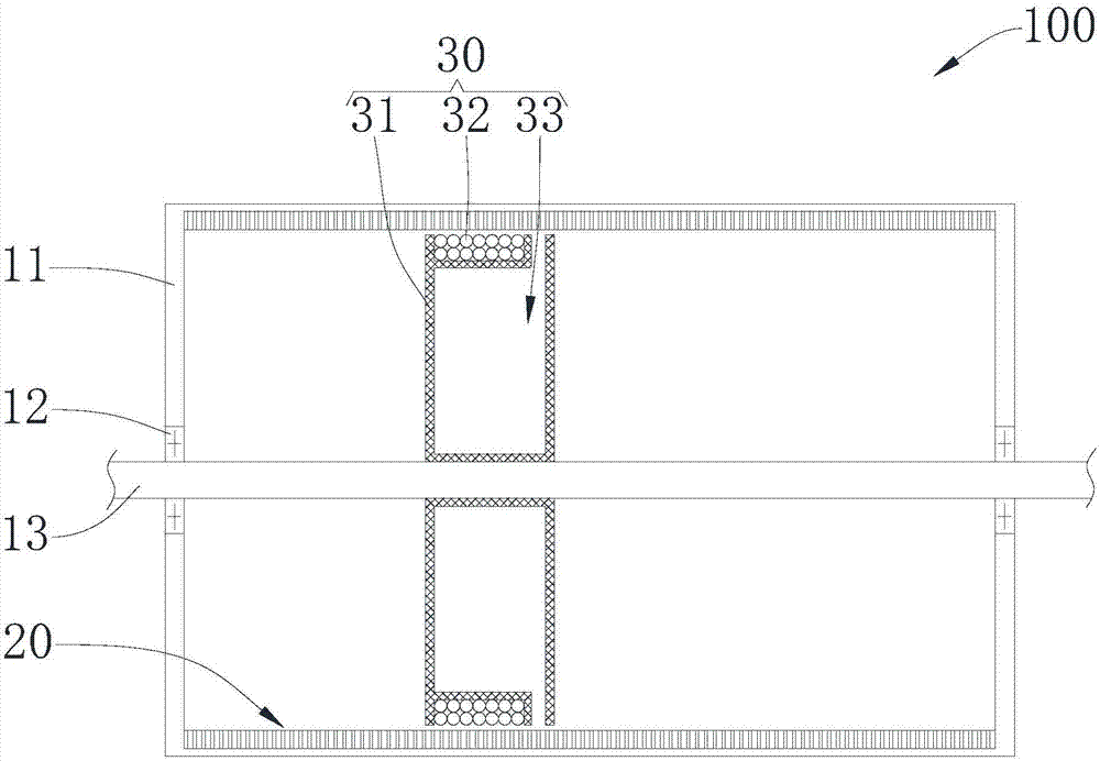
[0028] see Figure 1-Figure 3 , a fast-response linear motor 100 provided by an embodiment of the present invention includes a casing 11 , a stator 20 , a rotor 30 and a support shaft 13 ; the stator 20 is installed on the casing 11 , and the stator 20 is supported and protected by the casing 11 . The rotor 30 is slidably installed in the stator 20 so that the rotor 30 can move in the stator 20, and the rotor 30 is installed on the support shaft 13, the rotor 30 can be supported by the support shaft 13, and the rotor 30 can move along the support shaft 13. The support shaft 13 is installed in the casing 11 such that the casing 11 supports the support shaft 13 . The stator 20 includes a conductive sleeve made of conductive material. The rotor 30 includes a supporting frame 31 and a driving coil 32. The supporting frame 31 is installed on the supporting shaft 13, and the driving coil 32 is wound on the supporting frame 31. When the driving coil 32 is energized, the driving coil...

Embodiment 2

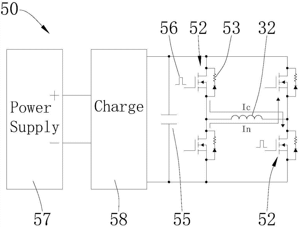
[0042] see Figure 4-Figure 10, the embodiment of the present invention provides a fast response linear motor 100a, including a casing 11, a stator 20, a rotor 30, a support shaft 13 and a control mechanism 40; the stator 20 is installed on the casing 11, and is supported and protected by the casing 11 Stator 20. The rotor 30 is slidably installed in the stator 20 so that the rotor 30 can move in the stator 20, and the rotor 30 is installed on the support shaft 13, the rotor 30 can be supported by the support shaft 13, and the rotor 30 can move along the support shaft 13. The support shaft 13 is installed in the casing 11 such that the casing 11 supports the support shaft 13 . The conductive sleeve of the stator 20 includes several magnetically conductive rings 21 and several spacer rings 22, and the magnetically conductive rings 21 and spacer rings 22 are alternately stacked. magnetism; then along the axial direction of the support shaft 13, one layer of magnetic conduction...

Embodiment 3

[0074] see Figure 11 and Figure 12 The difference between the fast-response linear motor 100b of this embodiment and the fast-response linear motor of Embodiment 1 is: each magnetic permeable ring 21 is provided with a number of first protruding teeth 23 protruding inward, and these first protruding teeth 23 are evenly distributed on the On each magnetic ring 21; the end 415 of the magnetic arm 41 away from the support shaft 13 is protrudingly provided with a number of second protruding teeth 416; along the radial direction of the stator 20: the distance between two adjacent first protruding teeth 23 is the same as the distance between two adjacent first protruding teeth 23 The distances between the two protruding teeth 416 are equal. First protruding teeth 23 are set on each magnetic conducting ring 21, and second protruding teeth 416 are provided on the magnetic permeating arm 41, which can form the function of a stepping motor, passing between the first protruding teeth ...


PUM


Abstract

The invention is suitable for the motor field, and provides a quick response linear motor, a control method of a quick response linear motor, and an integrated control chip. The quick response linear motor comprises a housing, a stator, a rotor, and a supporting shaft. The stator comprises a conductive sleeve, and the rotor comprises a supporting skeleton and a driving coil used for generating a driving magnetic field along the axial direction of the supporting shaft. The conductive sleeve of the stator of the quick response linear motor can be produced by adopting conductive materials, and the supporting skeleton of the rotor is provided with the driving coil in a coiled manner. When the current pulse passes through the driving coil, the induced current can be generated by the stator, and the magnetic field opposite to the above mentioned driving magnetic field can be generated, and then the rotor can be driven to move, and therefore the quick response can be realized. When the large instantaneous pulse current passes through the driving coil, the large power can be generated. The coiling direction of the driving coil is arranged around the axial direction of the supporting shaft, and the stator is in the shape of a sleeve, and therefore the size of the rotor can be small, and then the size of the linear motor is small.

Description

technical field [0001] The invention belongs to the field of motors, and in particular relates to a fast-response linear motor, a control method and an integrated control chip for the fast-response linear motor. Background technique [0002] Linear motor is also called linear motor. Its principle is: linear motor is a transmission device that directly converts electrical energy into linear motion mechanical energy without any intermediate conversion mechanism. It can be regarded as a rotating motor cut radially and developed into a plane. The side evolved from the stator is called the primary, and the side evolved from the rotor is called the secondary. In practice, the primary and secondary are manufactured to different lengths to ensure that the coupling between the primary and secondary remains constant over the required travel range. Linear motors can be short primary and long secondary, or long primary and short secondary. When the primary winding is connected to the...

Claims


Application Information

Patent Timeline
Patent Type & Authority Patents(China)
IPC IPC(8): H02K41/025H02P25/06
CPCH02K41/025H02P25/06
Inventor 刘华
Owner 刘华
Why Eureka
Try Eureka