Wiring equipment and microswitch terminals

A wiring equipment and terminal technology, applied in the direction of interconnection devices, ISDN systems, time-division multiplexing selection devices, etc., can solve problems such as difficulty, high cost, and excessive wiring lines

Active Publication Date: 2019-01-29
RUIJIE NETWORKS CO LTD
View PDF3 Cites 0 Cited by
  • Summary
  • Abstract
  • Description
  • Claims
  • Application Information

AI Technical Summary

Problems solved by technology

[0006] The embodiment of the present invention provides a wiring device and a micro-switching terminal, which are used to solve the problems of too many wiring lines, great difficulty and high cost in the existing wiring method

Method used


Image

  • Wiring equipment and microswitch terminals
  • Wiring equipment and microswitch terminals
  • Wiring equipment and microswitch terminals

Examples


Embodiment 1

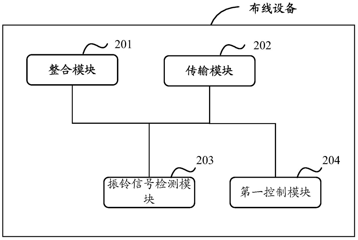
[0068] In order to solve the problems of too many wiring lines, great difficulty and high cost in the existing wiring method, Embodiment 1 of the present invention provides a wiring device, such as figure 2 As shown, it is a schematic structural diagram of a wiring device in Embodiment 1 of the present invention, including:

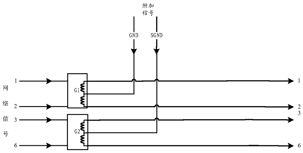
[0069] The integration module 201 is configured to superimpose N additional signals on the network signals transmitted by at least N+1 pairs of core wires of one network cable according to the relationship between one additional signal except the network signal and two pairs of core wires, so that the additional The signal and the network signal form an integrated signal; wherein, N is a positive integer, and the value of N is smaller than the logarithm of the core wires of the network cable.

[0070] The transmission module 202 is configured to transmit the integrated signal through a network cable.

[0071] Wherein, in an embodiment, one additional si...

Embodiment 2

[0137] Based on the same inventive concept, Embodiment 2 of the present invention provides a microswitch terminal, specifically, as Figure 7 As shown in , it is a schematic structural diagram of the microswitch terminal described in Embodiment 2 of the present invention, including:

[0138] The receiving module 701 is configured to receive an additional signal transmitted by a network cable other than the network signal and an integrated signal after the network signal is integrated;

[0139] The separation module 702 is used to separate N-way additional signals and Z-way network signals from the integrated signal; wherein, N is a positive integer, and the value of N is less than the logarithm of the core wire of the network cable, and the value of Z is micro The number of downlink ports of the switching terminal.

[0140] It should be noted that the microswitch terminal in Embodiment 2 of the present invention may be a device such as an ETP terminal installed at a terminal ...

Embodiment 3

[0195] Based on the same inventive concept, the embodiment of the present invention provides a wiring system, such as Figure 11 As shown, specifically, the wiring system may include:

[0196] The wiring device 1101 can be used to superimpose N channels of additional signals on the network signals transmitted by at least N+1 pairs of core wires of a network cable according to the relationship between one additional signal except the network signal and two pairs of core wires, so that the additional The signal and the network signal form an integrated signal; wherein, N is a positive integer, and the value of N is less than the logarithm of the core wire of the network cable; the integrated signal is transmitted to the microswitch terminal 1102 through the network cable;

[0197] The microswitch terminal 1102 can be used to receive additional signals other than network signals transmitted by a network cable and integrated signals after network signal integration; separate N add...


PUM


Abstract

The invention discloses wiring equipment and a micro-exchange terminal. According to the technical scheme of the invention, an additional signal (such as a current signal and / or a telephone signal) is integrated with a network signal transmitted by a network wire to form an integration signal. The integration signal is transmitted by the network wire, and then a receiving terminal can receive the integration signal by the network wire. Meanwhile, according to the integration signal, a corresponding network signal and a corresponding additional signal, (such as a power supply signal and a network signal, or a telephone signal and a network signal, or a power supply signal, a telephone signal and a network signal), can be obtained. Therefore, the problem in the prior art that the existing wiring method is excessive in wired circuits, large in difficulty and high in cost can be solved. Meanwhile, the network wiring complexity is greatly reduced, and the network wiring cost is lowered.

Description

technical field [0001] The invention relates to the field of weak current integrated wiring, in particular to wiring equipment and micro-switching terminals. Background technique [0002] With the continuous development of intelligent buildings, intelligent equipment is becoming more and more popular, which makes more and more communication lines and network lines required by intelligent buildings. For example, not only network signals need to be transmitted, but also power signals, telephone signals, integrated services digital network (ISDN) signals, fax signal modem (modulator-demodulator, MODEM) signals, etc. [0003] For example, taking the telephone signal as an example, for high-density intelligent buildings such as office buildings, office buildings, and electronic classrooms, each working position (station) needs to be equipped with a computer and a telephone for the Employees use it in their daily work. That is, a network signal and a telephone signal need to be ...

Claims


Application Information

Patent Timeline
Patent Type & Authority Patents(China)
IPC IPC(8): H04M11/06H04M7/12H04Q11/04H02G3/04
CPCH02G3/0443H04M7/1205H04M11/06H04M2207/08H04Q11/0428Y10S370/904
Inventor 陈继义
Owner RUIJIE NETWORKS CO LTD
Why Eureka
Try Eureka