
Method for preventing swirling slag from metallurgical casting and device therefor

A vortex and slag rolling technology, which is applied in metal processing equipment, mechanical cleaning, manufacturing tools, etc., can solve problems such as the difficulty of accurately grasping the specific gravity and center of the cone, the complexity of the suppressor molding process, and the rise of secondary oxidation pollutants. Reaching the effect of obvious vortex slag entanglement, eliminating vortex slag entrapment phenomenon, and improving cleanliness

Active Publication Date: 2018-07-20
SUZHOU UNIV
View PDF1 Cites 0 Cited by
  • Summary
  • Abstract
  • Description
  • Claims
  • Application Information

AI Technical Summary

Problems solved by technology

In 1984, U.S. Patent US4601415 introduced a pyramid-shaped molten steel eddy current suppressor, which is a polygonal cone made of refractory material with a specific gravity between molten steel and slag. There is a steel ball in the center of the cone to make it The fixed point of the cone is kept downward, and as the liquid steel level drops, the cone can gradually block the nozzle, prevent the generation of vortex flow and block slag, the disadvantage is that the specific gravity and center of the cone are not easy to accurately grasp, and the suppressor The processing industry is more complex
[0004] In general, in the existing technology, the sliding nozzle system has defects such as high cost, fixed installation position, converging vortex at the end of pouring, continuous pouring will cause secondary oxidation pollutants to rise, and other anti-rotation methods also have excessive excess steel. , negative measures to reduce the metal yield; therefore, it is necessary to develop a new device with simple design and easy implementation, which can effectively prevent the vortex, and the anti-swirl device has a long service life and has strong practical application value

Method used


Image

  • Method for preventing swirling slag from metallurgical casting and device therefor
  • Method for preventing swirling slag from metallurgical casting and device therefor
  • Method for preventing swirling slag from metallurgical casting and device therefor

Examples


Embodiment 1

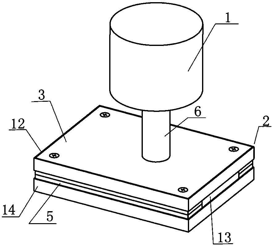
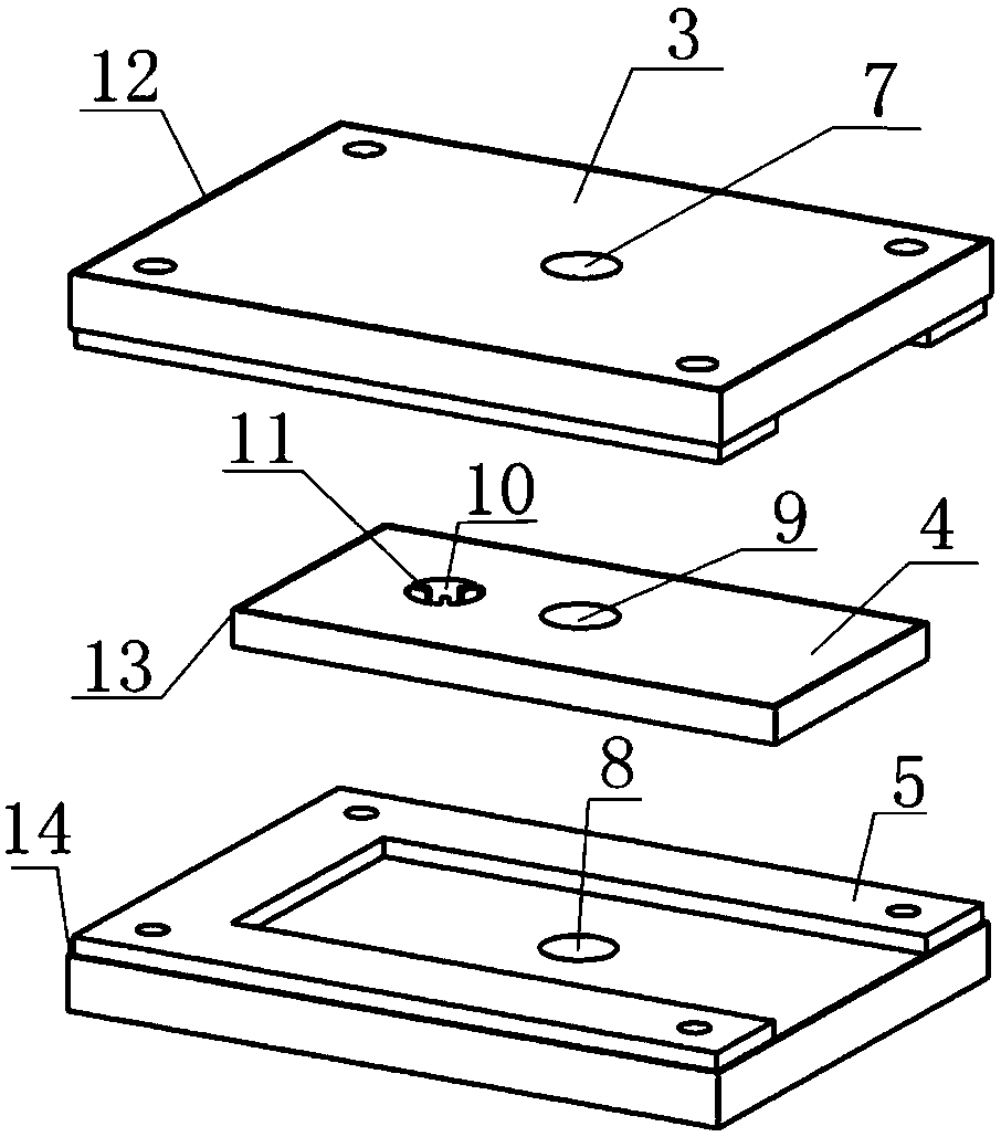
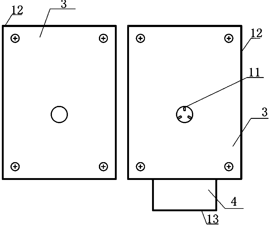
[0031] See attached Figure 1-2 , a device for preventing metallurgical reactor pouring from producing vortex slag, comprising a metallurgical reactor 1 and a pouring interface 2; the pouring interface includes an upper plate 3, a middle plate 4, and a lower plate 5; The outlet of the device is connected; the lower plate and the upper plate are connected by screws; the middle plate can slide relative to the upper plate and the lower plate; the sliding of the middle plate can be controlled by using the existing tie rod, which can be connected with the cylinder or the driver. Upper plate 3 is provided with upper plate tight hoop 12 around, middle plate 4 is surrounded with middle plate tight hoop 13, and lower plate 5 is surrounded with lower plate tight hoop 14; The thickness is 2mm, which can effectively avoid the cracking of the board, prevent the penetration of molten metal, and greatly increase the service life of the interface device. The upper plate 3 is provided with an...

Embodiment 2

[0037] The device for preventing metallurgical reactor pouring from producing vortex slag has the same structure as that of Embodiment 1, except that the second through hole 10 of the middle plate 4 is provided with 4-piece 90° arrangement of shields 11, which are symmetrically distributed, see Figure 4 ; The spacer and the middle plate are integrally formed, and the material is MgO-C; the metallurgical reactor is a continuous casting ladle.

[0038] A 250t continuous casting ladle in a steelmaking plant, the liquid level of the full ladle is 4.7m, and the diameter of the tap hole is 200mm. During the pouring of the continuous casting tundish on the continuous casting platform on the ladle, due to the limited standing time of the refining station, during the conventional pouring process , Relying on the automatic slag detection system to control the export of molten steel, the general amount of remaining steel is about 1.2t. Use the above-mentioned device for preventing vorte...

Embodiment 3

[0040] The device for preventing vortex slag from pouring in the metallurgical reactor is consistent with the structure of the first embodiment, except that the second through hole is provided with 5 pieces of baffles that are evenly distributed at 72°, the length of the baffles is 35mm, and the middle plate is relatively to the upper plate. Both the surface of the lower plate and the lower plate are provided with a lead powder layer, which is beneficial to increase the sliding of the middle plate. A 50t tundish in a steelmaking plant, with a tap hole diameter of 110mm, is used in a continuous casting crystallizer; the device for preventing metallurgical reactor pouring from producing vortex slag of the present invention is used to prevent metallurgical reactor pouring from producing vortex slag, using Example 1 In the pouring step, the vortex slag completely disappeared in the mid-term, and the amount of remaining steel was reduced by nearly 42%.


PUM

PropertyMeasurementUnit
lengthaaaaaaaaaa

Abstract

The invention discloses a method for preventing vortex slag from metallurgical pouring and a device used for the method, comprising a metallurgical reactor and a pouring interface; the pouring interface includes an upper plate, a middle plate and a lower plate; the upper and lower plates are provided with through holes; The middle plate is provided with two through holes, one of which is provided with a stop piece; the lower surface of the upper plate is provided with an upper groove, and the upper surface of the lower plate is provided with a lower groove; the middle plate is located on the upper groove and the lower groove In the space; the middle plate can slide relative to the upper plate and the lower plate. The method of the present invention is different from the existing vortex flow control mode. During the tapping process of the metallurgical reactor, the tangential movement speed of the vortex flow of molten steel is eliminated by changing the internal structure of the tapping hole, thereby significantly reducing the critical height of the vortex. , prevent the upper layer of steel slag from being sucked into the downstream reactor, and control the amount of slag.

Description

technical field [0001] The invention belongs to the technical field of metallurgical pouring, and in particular relates to a method for preventing vortex slag from being generated in the pouring process of a metallurgical reactor and a device used for the method. Background technique [0002] With the continuous development of high-quality steel and special performance steel, more stringent requirements are put forward for the quality of molten steel in steelmaking, refining and pouring. During the pouring process of metallurgical reactors (such as converters, ladles and tundishes), due to the influence of the initial flow state of molten steel, vortex flow will occur in the middle and late stages of pouring. The slag layer is entrained into the downstream reactor, and the broken slag layer particles will cause different sizes, some of which will be removed by floating up, and some fine particles will remain in the molten steel because they are difficult to remove, forming n...

Claims


Application Information

Patent Timeline
Patent Type & Authority Patents(China)
IPC IPC(8): B22D43/00
CPCB22D43/002
Inventor 屈天鹏王德永郝月莹郭瑞琪王慧华田俊苏丽娟袁子凯
Owner SUZHOU UNIV
Learn More