Industrial robot kinematic modelling method and system

A technology of robot kinematics and industrial robots, applied in manipulators, manufacturing tools, program control manipulators, etc., can solve the problems of lack of versatility and achieve the effect of strong versatility

Inactive Publication Date: 2016-05-25
国机智能科技有限公司
View PDF4 Cites 10 Cited by
  • Summary
  • Abstract
  • Description
  • Claims
  • Application Information

AI Technical Summary

Problems solved by technology
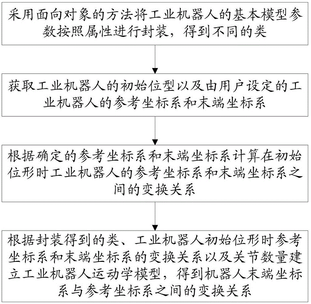
[0005] The technical problem to be solved by the present invention is to provide an industrial robot kinematics modeling method and system, which solves the problem of insufficient versatility of existing kinematics modeling methods

Method used


Image

  • Industrial robot kinematic modelling method and system
  • Industrial robot kinematic modelling method and system
  • Industrial robot kinematic modelling method and system

Examples


Embodiment 1

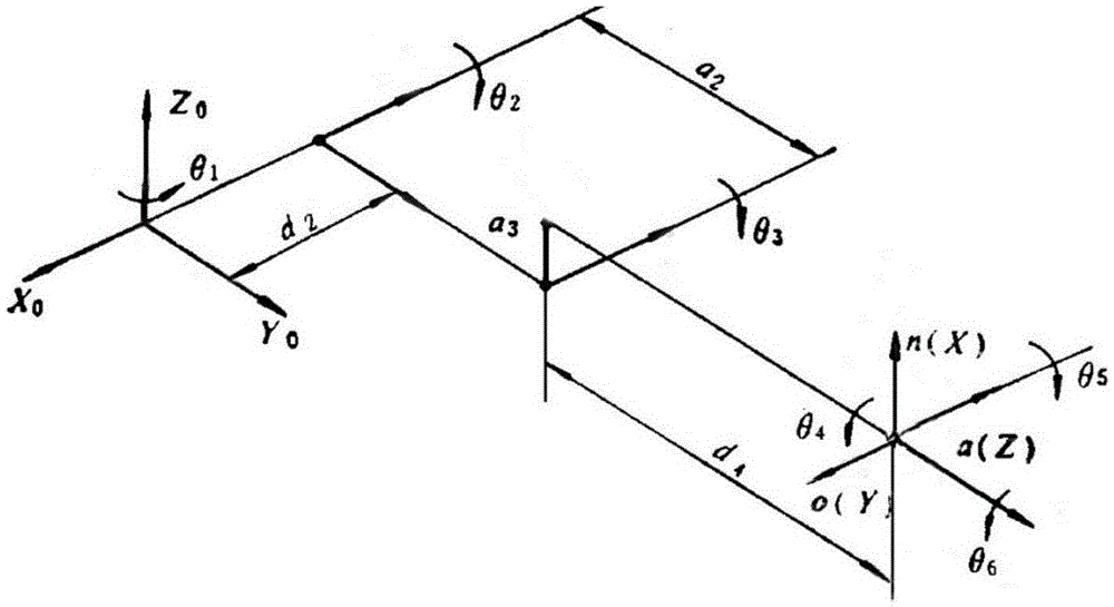
[0081] According to the industrial robot kinematics modeling method established in the present invention, the industrial robot composed of six rotary joints is used as the research object to carry out verification.

[0082] The robot structure is as figure 2 As shown, the current position is the initial configuration, the base coordinate is selected as the reference coordinate system S, and the end coordinate system T, and the directions of the two coordinate systems are consistent. The axis position of joint 1 is used as the origin of the reference coordinate system. where d 2 is the distance between the axis position of joint 2 along the negative direction of the x-axis of the reference coordinate system and the origin of the reference coordinate system; a 2 is the distance between the axis position of joint 3 and the origin of the reference coordinate system along the negative direction of the x-axis of the reference coordinate system; the axis positions of joints 4, 5, ...


PUM


Abstract

The invention relates to an industrial robot kinematic modelling method and an industrial robot kinematic modelling system. The method comprises the following steps: S1, encapsulating basic model parameters of an industrial robot according to attribute by adopting an object-oriented method so as to obtain different classes; S2, acquiring the initial position type of the industrial robot and a reference coordinate system and a tail end coordinate system of the industrial robot set by a user; S3, calculating the transformation relation between the reference coordinate system and the tail end coordinate system of the industrial robot at the initial position type according to the determined reference coordinate system and tail end coordinate system; S4, establishing a kinematic model of the industrial robot according to the classes obtained by encapsulating, the transformation relation between the reference coordinate system and the tail end coordinate system when the industrial robot is at the initial position type, and the number of joints, and obtaining the transformation relation between the tail end coordinate system and the reference coordinate system of the robot. According to the method and the system, the problem of insufficient universality of the existing kinematic modelling method is solved.

Description

technical field [0001] The invention relates to the technical field of robot modeling, in particular to an industrial robot kinematics modeling method and system. Background technique [0002] Robot kinematics describes the kinematic relationship between the robot joints and the rigid bodies that make up the robot. The joints are driven by the driver, and the relative motion of the joints leads to the movement of the connecting rod, so that the end can achieve the desired pose. When the robot is working, it needs to pass through the space. A series of points, these points constitute the working range of the robot, which is obtained by the kinematics positive solution, so the kinematics modeling of the robot is the basis of the robot control. [0003] With the development of robot application fields, robot operators are popularized, and robots themselves are diversified and multi-degree-of-freedom. Therefore, it is of great significance to carry out research on efficient, gen...

Claims


Application Information

Patent Timeline
Patent Type & Authority Applications(China)
IPC IPC(8): B25J9/04B25J9/16
CPCB25J9/046B25J9/1605B25J9/1607
Inventor 赵文灿
Owner 国机智能科技有限公司
Why Eureka
Try Eureka