Magnetic-levitation train levitation control device and method

A technology of suspension control and maglev trains, which is applied to electric vehicles, vehicle components, transportation and packaging, etc., can solve the problems of high cost and vehicle structure no longer adapting to the original line conditions, and achieve large volume and good comprehensive effect , the effect of improving usability

Active Publication Date: 2016-05-25
TONGJI UNIV
View PDF6 Cites 13 Cited by
  • Summary
  • Abstract
  • Description
  • Claims
  • Application Information

AI Technical Summary

Problems solved by technology

Obviously, the cost of such a large-scale transformation is high, and after the transformation, there will be problems such as the structure of the vehicle no longer adapting to the original line conditions.

Method used


Image

  • Magnetic-levitation train levitation control device and method
  • Magnetic-levitation train levitation control device and method
  • Magnetic-levitation train levitation control device and method

Examples


Embodiment

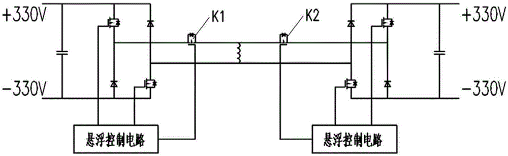
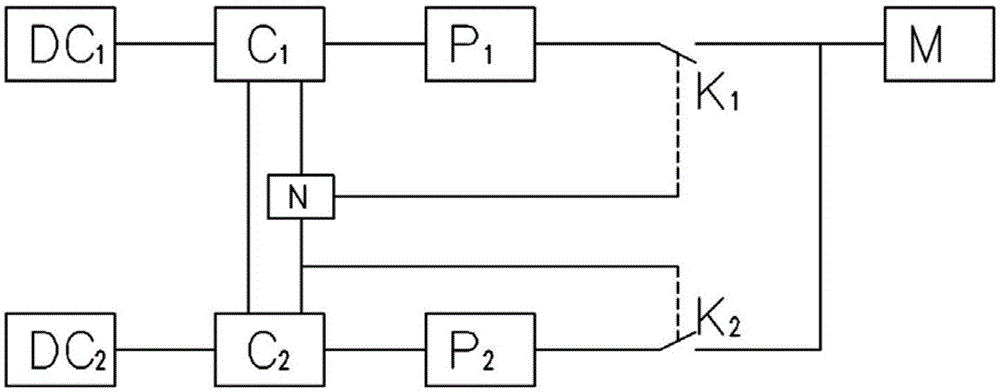
[0030] Such as figure 2 , image 3 As shown, a levitation control device for a maglev train is used to control the electromagnet of the maglev train. It includes two control units with the same structure and independent electricity. Switches K1, K2, power conversion circuits P1, P2 for generating the electromagnet current, auxiliary power supplies DC1, DC2 for supplying power to the control circuits C1, C2 and power conversion circuits P1, P2, the auxiliary power supplies DC1, DC2 are The mutually independent 660V DC power supplies supply power to the corresponding control circuits C1, C2 and power conversion circuits P1, P2 respectively. The output terminals of the power conversion circuits P1 and P2 are connected to the strobe power switches K1 and K2, the output power of the power conversion circuits P1 and P2 is controlled by the control circuits C1 and C2 of the control unit where they are located, and the strobe power switches K1 and K2 are fully controlled Electronic...

Embodiment example

[0035]H-type power conversion circuits P1 and P2 are respectively composed of charging circuit, input side support capacitor, discharge circuit, IGBT or MOSFET fully controlled power device and freewheeling diode; the main control chips of control circuits C1 and C2 adopt DSP and FPGA, The main function is to receive the suspension sensor signal on the electromagnet, calculate the expected current value of the electromagnet according to a certain control algorithm, and generate a PWM signal, which is output to the drive board of the H-type power conversion circuit. Among the two strobe power switches K1 and K2, the strobe power switch K1 can be opened or closed by the joint control of the control circuit C1 and C2. When the control circuit C1, the power conversion circuit P1 and the auxiliary power supply DC1 are all normal, the strobe power switch K1 is controlled by the control circuit C1. When any one of the control circuit C1, the power conversion circuit P1 and the auxilia...


PUM


Abstract

The invention relates to a magnetic-levitation train levitation control device to be used for controlling an electromagnet of a magnetic-levitation train. The device comprises two electrically independent control units which are of the same structure. The control units comprise control circuits (C1, C2), gating power switches (K1, K2) used for being connected with the same electromagnet, power conversion circuits (P1, P2) and auxiliary power supplies (DC1, DC2), wherein the output ends of the power conversion circuits (P1, P2) are connected with the gating power switches (K1, K2), the output power of the power conversion circuits (P1, P2) is controlled by the control circuits (C1, C2) of the corresponding control units, and switching on and off of the gating power switches (K1, K2) are controlled by the control circuits (C1, C2) of the two control units at the same time. Compared with the prior art, the device has the advantages that due to the fact that the two-in-one levitation controller is adopted, the usability of the magnetic-levitation train is improved, the circuit structure is simplified, and a good comprehensive effect is realized.

Description

technical field [0001] The invention relates to a maglev control device, in particular to a levitation control device and method for a maglev train. Background technique [0002] EMS (ElectroMagneticSuspension) maglev train is a new type of rail transportation, with outstanding features such as low operating noise, strong climbing ability, small turning radius, high safety and reliability, low operation and maintenance costs, and low construction cost. It uses electromagnetic suction to suspend the car body above the track, and maintains a non-contact state between the train and the track, which overcomes the contact wear between the two and reduces the running resistance. The suspension controller is the actuator to realize the suspension of the vehicle. It changes the size of the internal current of the suspension electromagnet according to the air gap between the suspension electromagnet and the track and the vertical motion acceleration of the electromagnet, thereby adju...

Claims


Application Information

Patent Timeline
Patent Type & Authority Applications(China)
IPC IPC(8): B60L13/06
CPCB60L13/06
Inventor 徐俊起林国斌荣立军吉文
Owner TONGJI UNIV
Why Eureka
Try Eureka