Fault detection method and detection device for coolant solenoid valve of scr system

A technology of SCR system and fault detection, which is applied to the electronic control of mufflers, exhaust devices, and exhaust treatment devices, etc., which can solve problems such as excessive engine emissions, difficulty in starting the engine, and poor fuel economy of the engine, so as to prevent Effects of Environmental Pollution

Active Publication Date: 2018-07-03
WEICHAI POWER CO LTD
View PDF7 Cites 2 Cited by
  • Summary
  • Abstract
  • Description
  • Claims
  • Application Information

AI Technical Summary

Problems solved by technology

The temperature at which the urea solution deteriorates is about 75°C. If the temperature of the engine coolant is above 80°C for a long time, the urea solution will deteriorate. The deterioration of urea itself will pollute the environment and cannot catalyze the reduction of NO. x , resulting in excessive engine emissions
[0006] Moreover, especially in cold regions, due to the low engine intake temperature and cooling water temperature, it is already difficult to start the engine. If there is a situation where the coolant solenoid valve switch is stuck or is not closed tightly, it will make it more difficult to start the engine; when there is When the switch of the coolant solenoid valve is stuck or is not closed tightly, a considerable part of the heat released by fuel combustion is used to heat the urea solution instead of doing work, causing the power of the engine to deteriorate. At the same time, the fuel consumption of the engine increases, and the fuel economy of the engine become worse

Method used


Image

  • Fault detection method and detection device for coolant solenoid valve of scr system
  • Fault detection method and detection device for coolant solenoid valve of scr system
  • Fault detection method and detection device for coolant solenoid valve of scr system

Examples


Embodiment Construction

[0037] The core of the present invention is to provide a fault detection method and detection device for a coolant solenoid valve in an SCR system. The method can timely detect the stuck or closed phenomenon of the coolant solenoid valve, avoid overheating and deterioration of the urea solution, and improve engine power performance.

[0038] In order to enable those skilled in the art to better understand the technical solution of the present invention, the present invention will be further described in detail below in conjunction with the SCR system coolant solenoid valve fault detection device, detection method, drawings and specific embodiments.

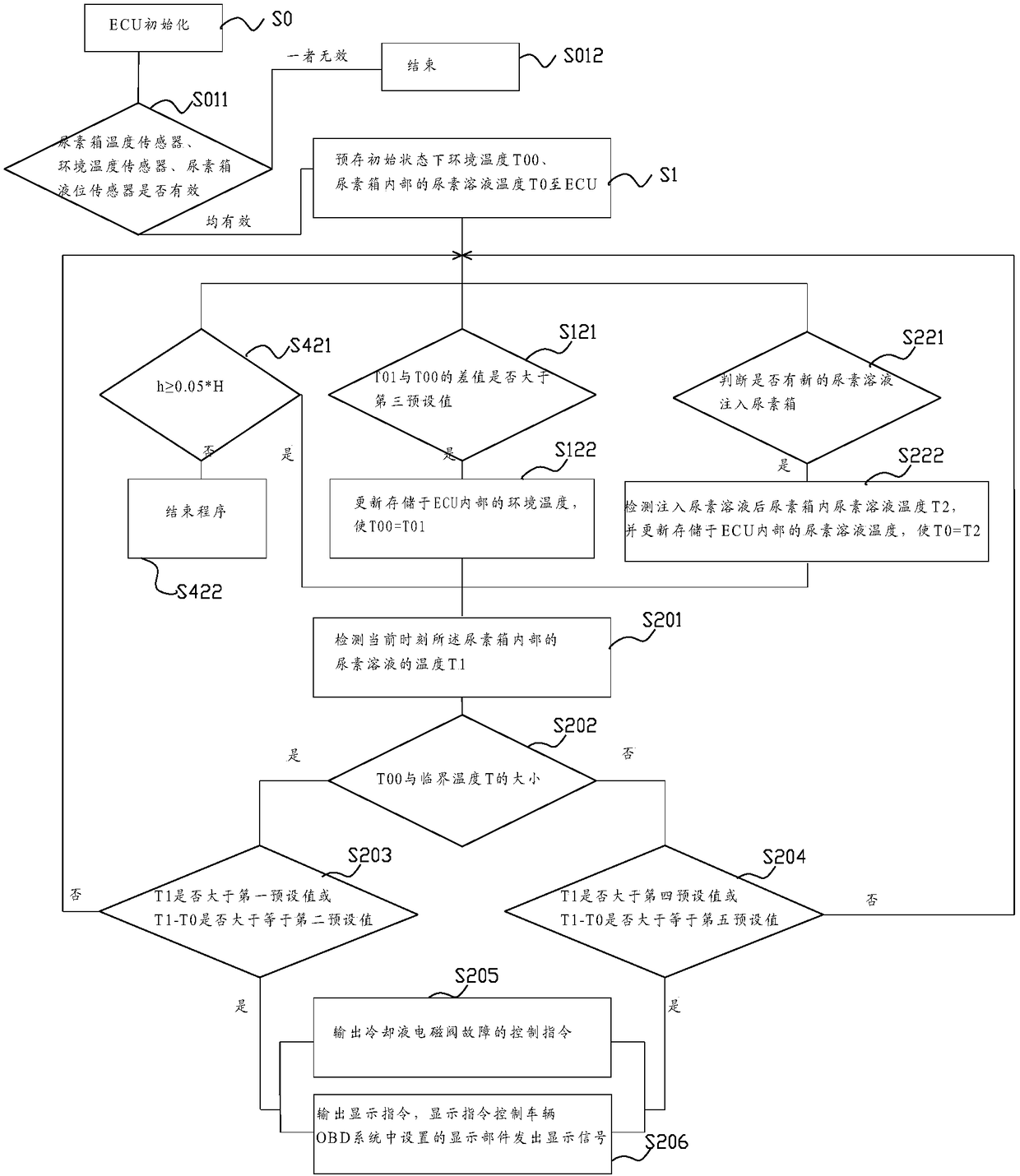
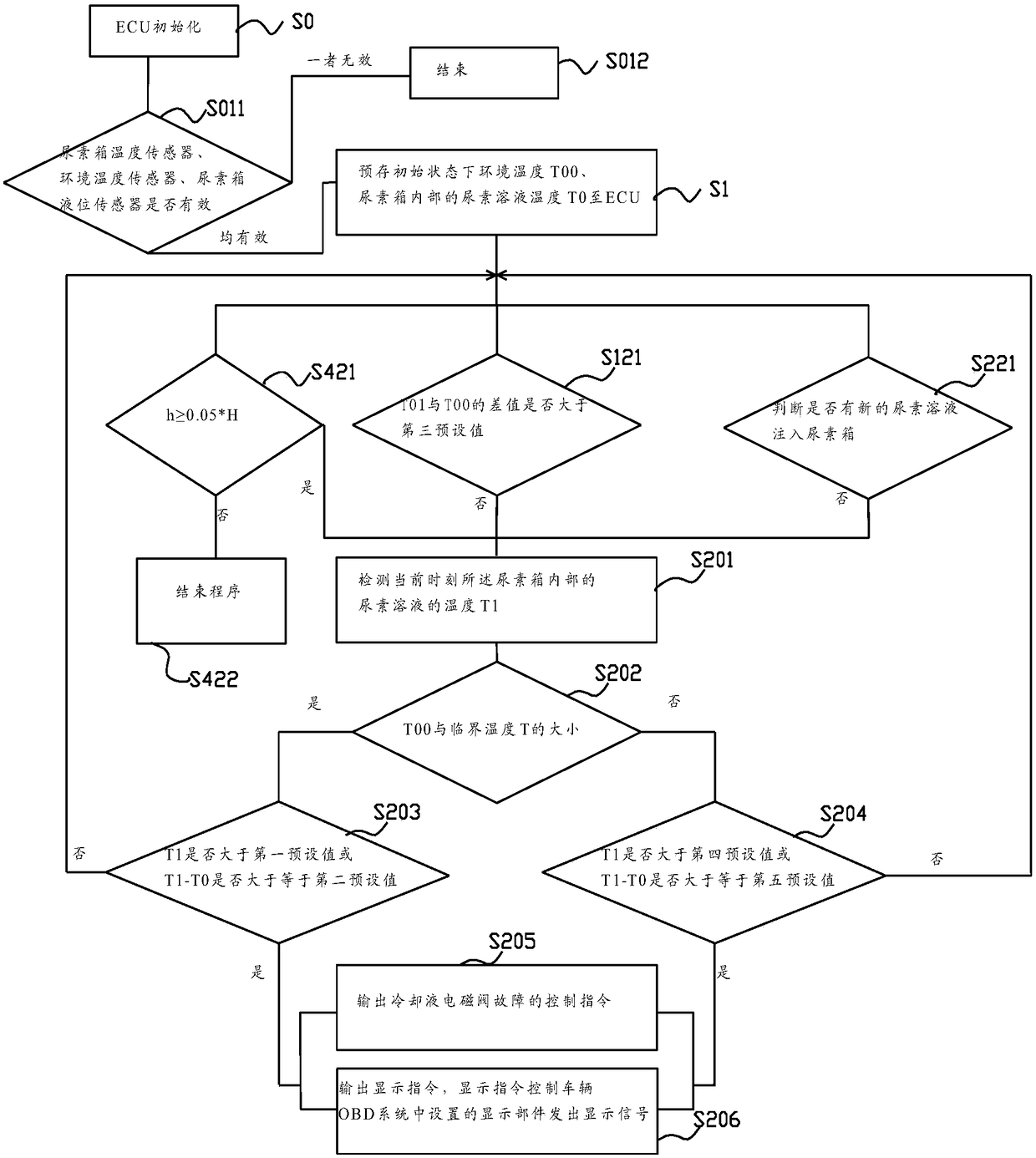
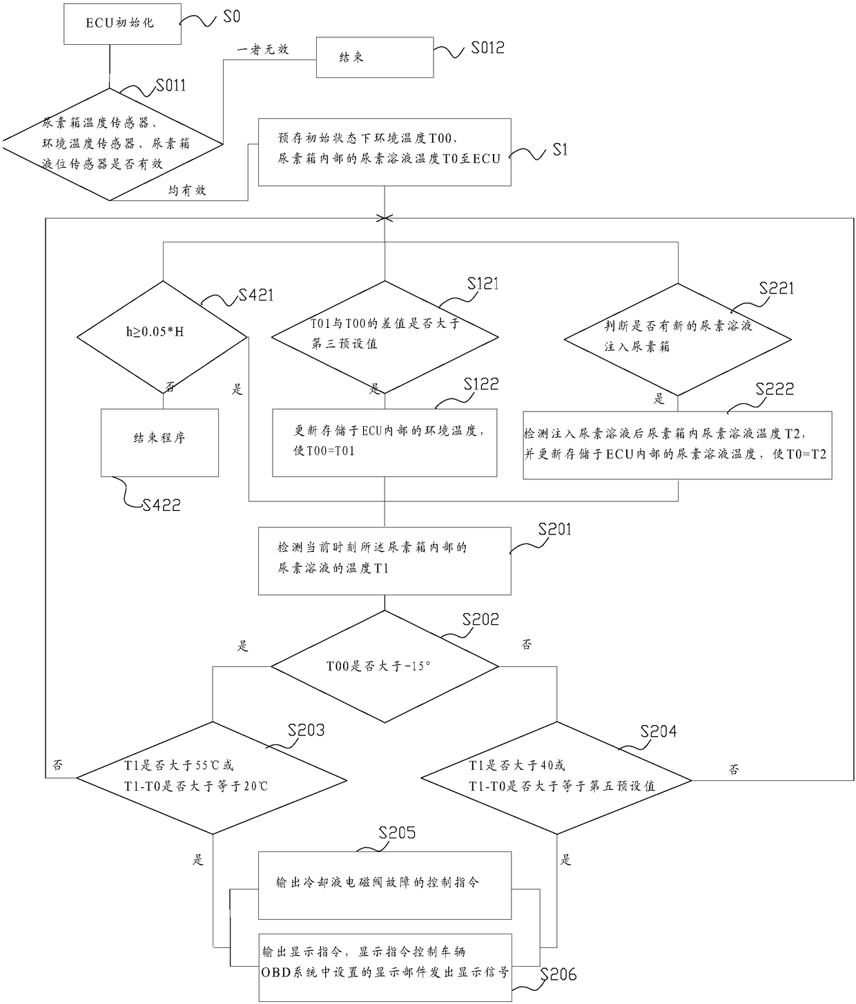
[0039] Please refer to figure 1 and figure 2 , figure 1 It is a partial flow diagram of the SCR system coolant electromagnetic valve fault detection method in a specific embodiment of the present invention; figure 2 It is a block flow diagram of another part of the fault detection method of the SCR system coolant solenoid valve ...


PUM


Abstract

The invention discloses a fault detection method and detection device for an SCR system cooling liquid electromagnetic valve. The method specifically comprises the steps that an ECU is initialized, and the environment temperature T00 under an initial state and the temperature T0 of a urea solution in a urea box are prestored to the ECU; the temperature T1 of the urea solution in the urea box at the current moment is detected; whether T1 is larger than a first preset value or whether T1-T0 is larger than or equal to a second preset value is judged at the environment temperature T00 stored in the ECU, and if one of judging results is yes, a cooling liquid electromagnetic valve fault control command is output. According to the detection method, hardware defects of the cooling liquid electromagnetic valve are reasonably judged according to the temperature of the urea solution and the temperature changing difference value, the judging results can be reported to a driver to prompt the driver that the cooling liquid electromagnetic valve is blocked or not switched off, therefore, the driver can replace the cooling liquid electromagnetic valve with a new one in time, and the method is beneficial for preventing environmental pollution and keeping the good economy and dynamic properties of an engine.

Description

technical field [0001] The invention relates to the technical field of electromagnetic control, in particular to a fault detection method and a detection device for a coolant solenoid valve of an SCR system. Background technique [0002] As a kind of power machinery, diesel engine has made outstanding contributions to the development of society, but it also causes environmental pollution. With the increasingly stringent national regulations, the requirements for diesel engine emissions are getting higher and higher, and it is becoming more and more difficult to achieve emission compliance only by improving engine technology. In this case, the SCR after-treatment system is introduced. [0003] The basic working principle of the SCR system: the exhaust gas flows out of the turbocharger and enters the exhaust pipe, and at the same time, the urea injection unit installed on the exhaust pipe sprays a certain amount of urea aqueous solution into the exhaust pipe in the form of mis...

Claims


Application Information

Patent Timeline
Patent Type & Authority Patents(China)
IPC IPC(8): F01N11/00
CPCF01N3/2066F01N11/00Y02A50/20Y02T10/40
Inventor 施泰峰刘玉伟孙世强
Owner WEICHAI POWER CO LTD
Why Eureka
Try Eureka