
Speed-increasing impeller for wind power generation

A technology for impellers and blades, which is applied in the field of speed-increasing impellers for wind power generation. It can solve the problems of rapid rotation of the blades, large centrifugal force, lower safety factor of the whole machine operation, and prone to speeding phenomenon, etc., so as to improve work efficiency, reduce system errors, and The effect of high reliability

Active Publication Date: 2018-04-10
李勇强
View PDF7 Cites 0 Cited by
  • Summary
  • Abstract
  • Description
  • Claims
  • Application Information

AI Technical Summary

Problems solved by technology

However, in the actual application process, especially for the application of high-power models, there will be disadvantages, which are manifested in the following points: (1) The speed of the wind wheel is low, which cannot reach the speed required by the generator for power generation
(2) The requirements for the selection of blade materials are high, and the centrifugal force of the rapid rotation of the blades is large, and the phenomenon of speeding is prone to occur under the action of strong winds, which greatly reduces the safety factor of the whole machine operation
(3) A direct drive generator with low speed is required, the generator is large in size, high in cost and heavy in weight

Method used


Image

  • Speed-increasing impeller for wind power generation
  • Speed-increasing impeller for wind power generation
  • Speed-increasing impeller for wind power generation

Examples


Embodiment Construction

[0027] The specific implementation manner of the present invention will be described below in conjunction with the accompanying drawings.

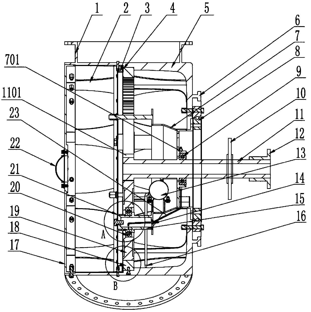
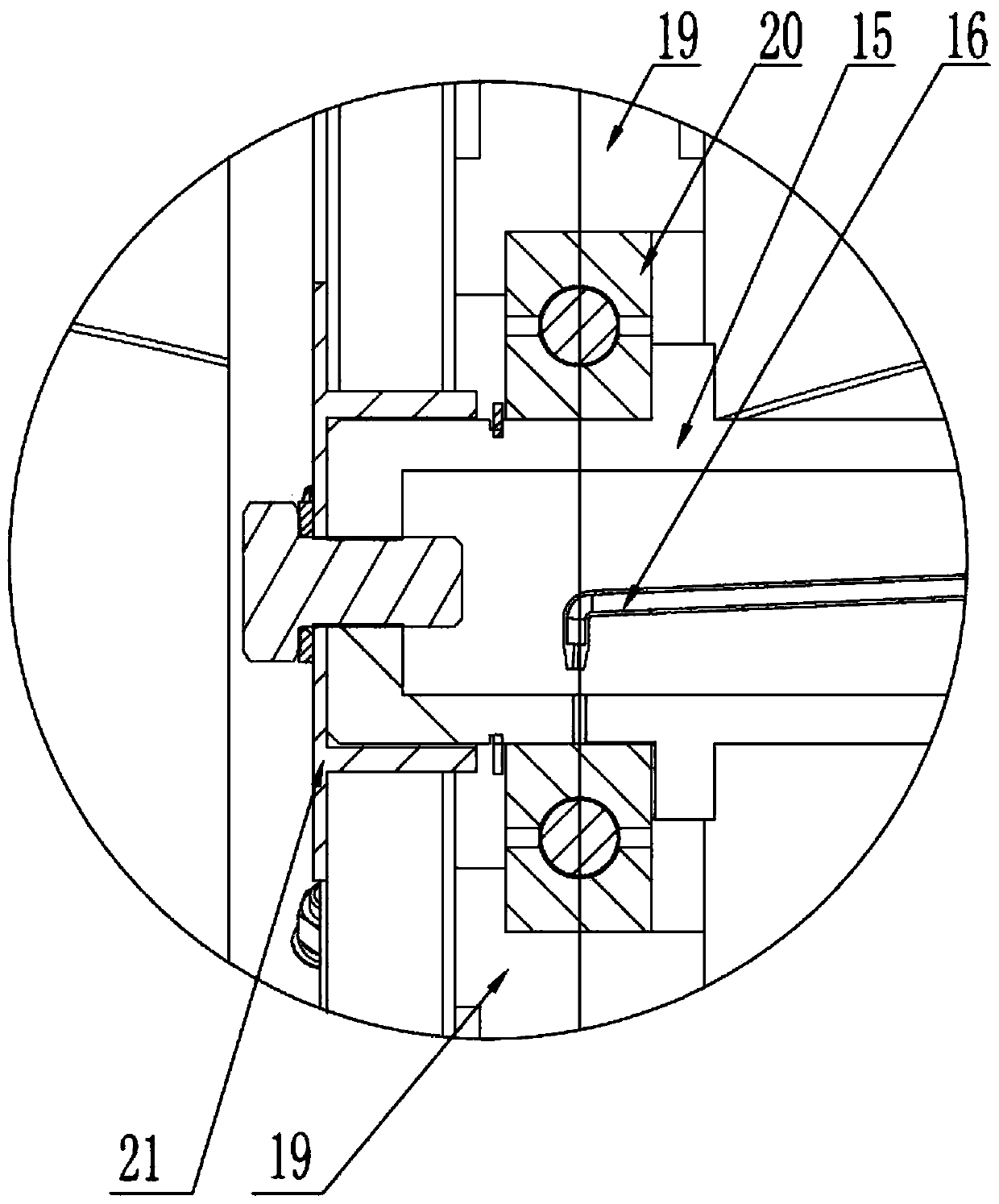
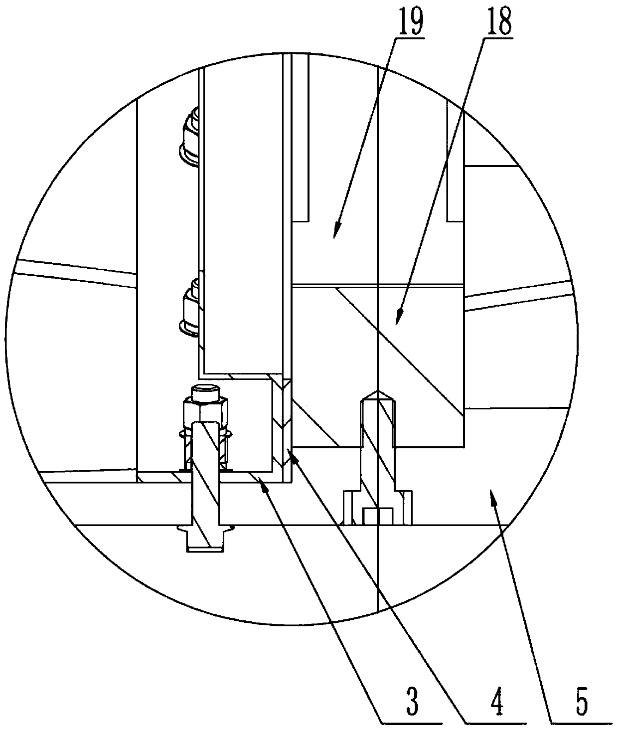
[0028] Such as figure 1 , figure 2 , image 3 , Figure 4 and Figure 5 As shown, a speed-increasing impeller for wind power generation includes an impeller cylinder 5, a plurality of blade bases 1 for connecting blades are evenly distributed on the outer wall of the impeller cylinder 5, and a ring gear 18 is fixed on the inner wall of the impeller cylinder 5 , a plurality of planetary gears 19 are meshed with the inner ring of the ring gear 18, and each planetary gear 19 is meshed with the sun gear 1101; the center of each planetary gear 19 is fitted with the planetary shaft 15, and the outer ring of each planetary shaft 15 is fitted with In the second bearing 20, one end of each planet wheel shaft 15 is connected to one end of the planetary carrier 7 to form a whole, the other end of the planetary carrier 7 is matched with the inner...


PUM


Abstract

The invention relates to a speed acceleration impeller for wind power generation. The speed acceleration impeller comprises an impeller cylinder body, wherein a plurality of blade bases used for connecting blades are uniformly distributed on the outer wall of the impeller cylinder body; a gear ring is fixedly connected onto the inner wall of the impeller cylinder body; a plurality of planetary wheels are engaged in the inner ring of the gear ring; each planetary wheel is engaged with a sun wheel; one end of each planetary wheel shaft is connected with one end of a planetary rack; the other end of the formed integral planetary rack is matched with the inner circle of a rotary bearing; the outer circle of the rotary bearing is connected with the end part of the impeller cylinder body; the other end of each planetary wheel shaft is fixedly connected with a planetary rack fixing ring; one end of the sun wheel shaft is connected with the sun wheel to form a whole; the other end of the sun wheel shaft penetrates through the planetary rack and is connected with the output end of a power generator through a shaft coupler. The speed acceleration impeller has the advantages that the blade torque and the centrifugal force generated when the impeller fast rotates are reduced; meanwhile, the service life of each blade is prolonged; the operation reliability of the whole machine system is improved; the size of the power generator is reduced; the weight and the related cost of the power generator are reduced.

Description

technical field [0001] The invention relates to the field of wind power generation equipment, in particular to a speed-increasing impeller for wind power generation. Background technique [0002] At present, as far as traditional wind power generation is concerned, its technology is not mature enough and has many shortcomings, especially in the construction of power stations, low wind speed start-up and distributed applications. Invest a large amount of money in the construction of long-distance transmission lines, such as the recently launched "four AC and four direct" UHV project construction, with an investment of 173.7 billion yuan. [0003] In order to overcome the above-mentioned problems of traditional wind power generation, a new type of wind power generation technology such as narrow tube wind power generation is derived. Compared with vertical axis wind turbines, it has the advantages of gathering wind energy, increasing pressure and increasing speed, and improvin...

Claims


Application Information

Patent Timeline
Patent Type & Authority Patents(China)
IPC IPC(8): F03D1/06
CPCF03D1/06Y02E10/72
Inventor 李勇强谢玉琪汪旭吴飞徐莉
Owner 李勇强
Learn More