Mechanical locking structure for leveling cylinder

A technology of mechanical locking and leveling oil cylinders, which is applied in the direction of mechanical equipment, fluid pressure actuators, servo meter circuits, etc., can solve the problems of mechanical locking structure difficulties, etc., and achieve the effect of simple structure, wide application and small friction

Inactive Publication Date: 2016-05-25
BEIJING XINLI MACHINERY
View PDF7 Cites 6 Cited by
  • Summary
  • Abstract
  • Description
  • Claims
  • Application Information

AI Technical Summary

Problems solved by technology

Due to structural limitations, it is very difficult to design a mechanical locking structure in the limited space of the hydraulic cylinder

Method used


Image

  • Mechanical locking structure for leveling cylinder
  • Mechanical locking structure for leveling cylinder

Examples


Embodiment Construction

[0026] The preferred embodiments of the present invention will be described below in conjunction with the accompanying drawings. It should be understood that the preferred embodiments described here are only used to illustrate and explain the present invention, and are not intended to limit the present invention.

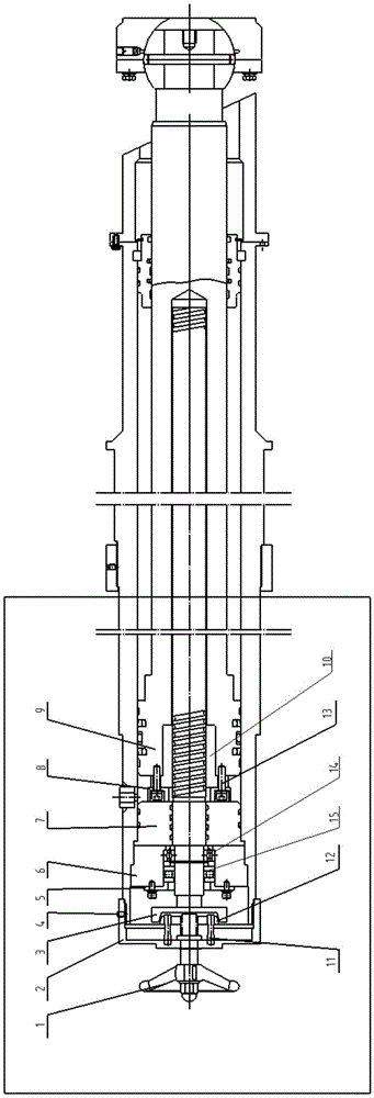
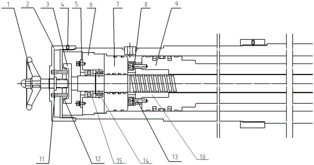
[0027] Such as Figure 1-2 As shown, a mechanical locking structure of a leveling oil cylinder, which includes a hydraulic cylinder, a piston rod 9 is arranged inside the hydraulic cylinder, the piston rod 9 and the piston are integrally formed, and a rolling screw pair 10, guide Cover 7, screw gland 6 and screw mechanism. The screw mechanism locks with the piston rod that holds the ball screw pair together, regardless of the position the piston rod is extended or retracted to. Specifically, the screw mechanism includes a handle 1 , a brake disc 12 and a screw rod 11 . The internal thread of the brake disc 12 cooperates with the external thread of the handle 1, an...


PUM


Abstract

The invention discloses a mechanical locking structure for leveling cylinder. The mechanical locking structure for leveling cylinder comprises a hydraulic cylinder and a screw mechanism, wherein a piston rod is arranged in the hydraulic cylinder; the piston rod and piston are integrally formed; the piston rod is fixedly connected with a ball screw pair; the ball screw pair is connected with the upper part of the hydraulic cylinder in the operational process in the hydraulic cylinder; the middle part of the piston rod is provided with a containing part; the ball screw pair in the hydraulic cylinder penetrates through the containing part; the piston rod is fixedly connected with the ball screw pair; one end of the ball screw pair is provided with a concave disk; and the screw mechanism can compact the concave disk and lock the ball screw pair in any position in the whole stroke of the hydraulic cylinder, so that the piston rod cannot retract.

Description

technical field [0001] The invention relates to a mechanical locking structure mainly used in hydraulic cylinders, in particular to a mechanical locking structure of a leveling oil cylinder. Background technique [0002] On many vehicles, the hydraulic cylinder is mostly used as the support of the vehicle in the working state, and the hydraulic cylinder is used to support the weight of the whole vehicle to complete the work. We develop a vehicle to ensure the wind resistance of the vehicle in working condition. The 4 outriggers can be mechanically locked to ensure that they will not shrink under support conditions. [0003] Hydraulic cylinders are always under load during operation. Therefore, it is necessary to solve the problem that the supporting legs (commonly known as soft legs) cannot bear the force caused by the leakage of the hydraulic cylinder during operation. For vehicles that need to work or keep the hydraulic cylinder supporting time for more than 24 hours, pr...

Claims


Application Information

Patent Timeline
IPC IPC(8): F15B15/26
CPCF15B15/264F15B2211/72
Inventor 李朝辉曹莲君
Owner BEIJING XINLI MACHINERY
Why Eureka
Try Eureka