
Identifiable light-emitting diode (LED) energy-saving lamp

A technology of LED energy-saving lamps and signs, which is applied in the direction of lamp shades, cooling/heating devices of lighting devices, lighting and heating equipment, etc., which can solve problems such as violation of environmental protection, short life, and inability to trace factory information, and achieve rapid ventilation and heat dissipation Effect

Inactive Publication Date: 2016-05-25
SUZHOU JIAYIDA ELECTRICAL APPLIANCES
View PDF5 Cites 0 Cited by
  • Summary
  • Abstract
  • Description
  • Claims
  • Application Information

AI Technical Summary

Problems solved by technology

[0002] Traditional incandescent lamps, high-pressure sodium lamps, and electrodeless lamps consume high energy and have short lifespan. Under the environment of global resource constraints, their production has been gradually banned by governments of various countries. The replacement products are electronic energy-saving lamps. Although electronic energy-saving lamps have improved the energy-saving effect , but due to the use of many heavy metal elements that pollute the environment, it is contrary to the general trend of environmental protection
With the rapid development of LED technology, LED lamps have gradually become the best choice for new green lighting. They are far superior to traditional lighting products in terms of luminous principle, energy saving, and environmental protection. However, the temperature rise of LED lamps is relatively high during use. High, heat dissipation has naturally become a major technical problem. Once the heat dissipation structure is unreasonably designed, it will definitely affect the service life of the LED lamp. In addition, because there is no identification part on the existing LED lamp, once the LED lamp has a problem, it cannot be traced back to the factory. information

Method used

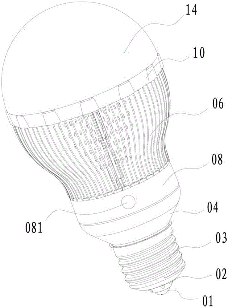
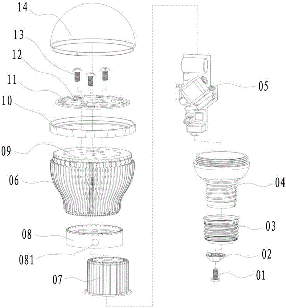
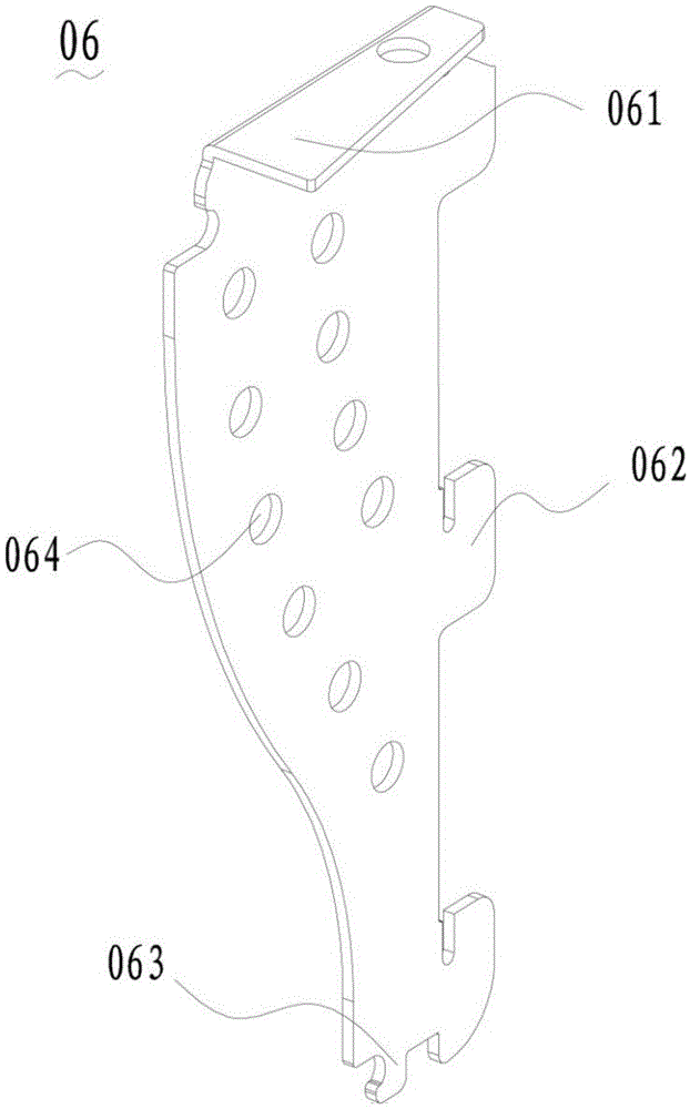

Image

  • Identifiable light-emitting diode (LED) energy-saving lamp
  • Identifiable light-emitting diode (LED) energy-saving lamp
  • Identifiable light-emitting diode (LED) energy-saving lamp

Examples


Embodiment Construction

[0016] The present invention will be further described in detail below in conjunction with the accompanying drawings, so that those skilled in the art can implement it with reference to the description.

[0017] like figure 1 As shown in -3, the present invention provides an identifiable LED energy-saving lamp, including: a column-shaped ventilator 07, a radiator 09 coaxially sleeved outside the ventilator 07, and a radiator 09 placed outside the radiator 09. The aluminum substrate 11 on the top surface of the aluminum substrate 11, a number of LED lamp beads 12 attached to the top surface of the aluminum substrate 11, the control circuit board 05 placed inside the ventilator 07, the control circuit board 05 One end of the aluminum substrate 11 is electrically connected to the LED lamp bead 12, the upper part of the aluminum substrate 11 is covered with a lampshade 14, and the bottom of the lampshade 14 is sleeved with a cover ring 10, and the material of the lampshade 10 is p...


PUM


Abstract

The invention discloses an identifiable light-emitting diode (LED) energy-saving lamp, comprising a cylinder-shaped air funnel, a radiator sleeved outside the air funnel in a coaxial way, an aluminum substrate arranged on the top end surface of the radiator, a plurality of LED lamp beads arranged on the top end surface of the aluminum substrate in a fitting way, and a control circuit board arranged in the air funnel, wherein one end of the control circuit board is electrically connected with the LED lamp beads; a plurality of ventilating slots are formed side by side in the air funnel at equal intervals; a plurality of cooling fins which are in a one-to-one correspondence relationship with the ventilating slots are arranged outside the radiator; the bottom of the radiator is connected with the upper part of a locating seat in a blocking way; an identification part is arranged outside the locating seat. The identifiable LED energy-saving lamp provided by the invention is safe, reliable, efficient and energy-saving, and has functions of rapid ventilation and heat dissipation.

Description

technical field [0001] The invention relates to the technical field of LED lamps, in particular to an identifiable LED energy-saving lamp. Background technique [0002] Traditional incandescent lamps, high-pressure sodium lamps, and electrodeless lamps consume high energy and have short lifespan. Under the environment of global resource constraints, their production has been gradually banned by governments of various countries. The replacement products are electronic energy-saving lamps. Although electronic energy-saving lamps have improved the energy-saving effect , but due to the use of many heavy metal elements that pollute the environment, it is contrary to the general trend of environmental protection. With the rapid development of LED technology, LED lamps have gradually become the best choice for new green lighting. They are far superior to traditional lighting products in terms of luminous principle, energy saving, and environmental protection. However, the temperatu...

Claims


Application Information

Patent Timeline
IPC IPC(8): F21K9/232F21V3/04F21V17/16F21V23/00F21V29/74F21V29/83F21Y115/10
CPCF21V3/06F21V17/16F21V23/00F21V29/74F21V29/83
Inventor 朱桂林
Owner SUZHOU JIAYIDA ELECTRICAL APPLIANCES
Learn More