
A ventilation filter device for rail transit

A filter device and rail transit technology, which is applied to electrical equipment casings/cabinets/drawers, casings/cabinets/drawer components, electrical components, etc., which can solve the problem of insufficient heat dissipation, difficult maintenance, and regular cleaning of electromagnetic components. problems, to achieve good ventilation and heat dissipation effects, simple and convenient production, and reduce labor costs

Active Publication Date: 2020-01-10
ZHUZHOU CSR TIMES ELECTRIC CO LTD
View PDF5 Cites 0 Cited by
  • Summary
  • Abstract
  • Description
  • Claims
  • Application Information

AI Technical Summary

Problems solved by technology

Moreover, when the vehicle is running, the cabinet body will be under negative pressure, which will cause a large amount of dust or rain and snow to be sucked into the cabinet body through the heat dissipation holes, resulting in device burnout, affecting the normal operation of electrical equipment, making maintenance costs high, and in severe cases even Affect the safe operation of the train
[0004] (2) Poor cooling performance
In order to achieve filtering, some products can only reduce the size and number of heat dissipation holes, which in turn leads to insufficient heat dissipation of electromagnetic components such as transformers and reactors in electrical equipment, poor heat dissipation, and equipment overheating, resulting in device burnout and affecting The normal operation of electrical equipment makes the maintenance cost high, and even affects the safe operation of the train in severe cases
[0005] (3) Difficult to maintain
However, the existing products are just not easy to maintain and need to be cleaned regularly, which increases maintenance costs
For example, a louver panel design in the prior art, when the vehicle is driving in the winter wind and snow weather in Northeast China, rain, snow, sand and dust enter the cabinet through the louver hole, because the local temperature is low, the rain, snow and sand and dust cannot be discharged from the bottom in time Cabinet
If it is not maintained in time, rain, snow and dust will gradually accumulate in the device. When the snow melts into water, wet sand and mud will be formed, which will cause the insulation performance of the device to decline, and eventually cause the device to burn out.

Method used


Image

  • A ventilation filter device for rail transit
  • A ventilation filter device for rail transit
  • A ventilation filter device for rail transit

Examples


Embodiment Construction

[0034] The present invention will be described in further detail below in conjunction with specific embodiments and accompanying drawings.

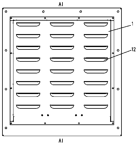
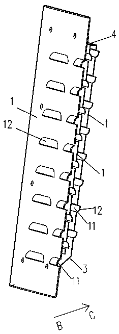
[0035] Such as Figure 1 to Figure 4As shown, the present invention provides a kind of ventilation filtering device that is used for rail transit, is installed on the cabinet of train electric equipment, comprises more than two ventilation filter plates 1 that are arranged in parallel from outside to inside (direction from outside to inside is the same as figure 2 , image 3 The direction of arrow BC in middle is the same), and there is a space between two adjacent ventilation filter plates 1 to form an airflow buffer interlayer 2, and each ventilation filter plate 1 is provided with a plurality of ventilation filter parts 11 arranged in an array, corresponding The ventilation filter parts 11 adjacent to the two ventilation filter plates 1 are alternately arranged to form a zigzag airflow channel, and the air passes through the ventilat...


PUM


Abstract

The present invention disclosed a ventilation filter device for rail transit, including two or more ventilated filter plates arranged from the outside to the inside to the inside.A variety of ventilation filtration departments are arranged on the ventilation filter plate. The ventilation filtering part of the two adjacent ventilation filter plates is staggered to form a tortuous airflow channel.The airflow buffer mezzanine to complete the ventilation filtration.The present invention has the advantages of simple structure, convenient production, low cost, can take into account efficient ventilation and efficient filtering, and avoid maintenance.

Description

technical field [0001] The invention mainly relates to the field of rail transit equipment, in particular to a ventilation filter device for rail transit. Background technique [0002] With the development of society, rail transit vehicles have extended in all directions, especially domestic railroads have spread all over the country. As we all know, when electrical equipment is working, the transformers and reactors installed in the products are all heating devices, which generate a lot of heat. The failure rate of electrical products will increase exponentially with the increase of ambient temperature, and the service life will decrease exponentially with the increase of ambient temperature. Due to the limitation of installation space, electromagnetic components such as transformers and reactors in electrical equipment adopt natural cooling design, and interact with the air outside the cabinet through cooling holes to improve heat dissipation performance. The following t...

Claims


Application Information

Patent Timeline
Patent Type & Authority Patents(China)
IPC IPC(8): H05K5/02B61C17/04
CPCH05K5/0213B61C17/04H05K5/03
Inventor 颜艳娇王佳佳罗国永饶沛南魏文海徐文龙李强勤唐勇军邹建军赵翔宇
Owner ZHUZHOU CSR TIMES ELECTRIC CO LTD
Learn More