
Combustor for gas turbine and flame combustion method

A gas turbine and burner technology, which is applied in the direction of combustion methods, combustion chambers, combustion equipment, etc., can solve the problems of combustion stability tempering, combustion instability, and low pollution emissions, and achieve strong combustion stability and enhanced combustion stability , Low NOx emission effect

Active Publication Date: 2016-05-25
SHANGHAI ELECTRIC GAS TURBINE CO LTD
View PDF10 Cites 6 Cited by
  • Summary
  • Abstract
  • Description
  • Claims
  • Application Information

AI Technical Summary

Problems solved by technology

Partial premix duty design can reduce NOx emissions, but it has problems such as combustion stability and backfire
In addition, the duty level and the premixing level are graded but not partitioned, which easily couples the combustion process of uniform mixing with the acoustic characteristics of the combustion chamber, resulting in the problem of unstable combustion
The existing vortex combustion technology can form a stable on-duty flame in the concave cavity, which has the characteristics of low pollution emission, wide combustion stability range, and high fuel-lean flameout performance. However, the outstanding disadvantage of this combustion technology is due to the existence of the concave cavity. It is easy to form the noise generated by the coupling of the flow characteristics and the heat release of the combustion chamber

Method used


Image

  • Combustor for gas turbine and flame combustion method
  • Combustor for gas turbine and flame combustion method
  • Combustor for gas turbine and flame combustion method

Examples


Embodiment 1

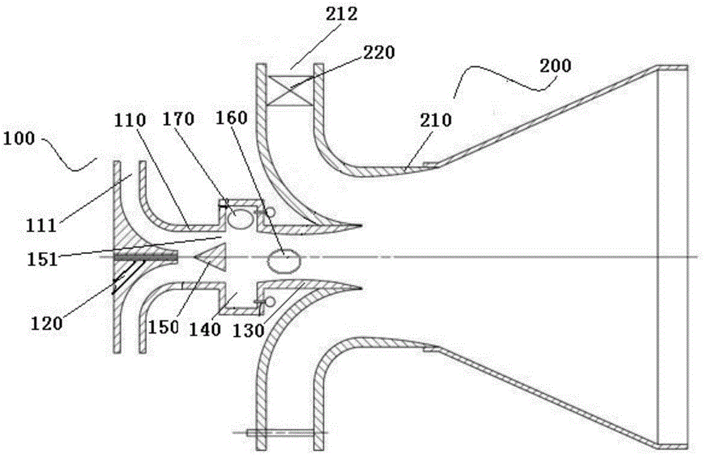
[0049] Such as figure 1 As shown, the burner for the gas turbine in this embodiment includes a connected central duty burner 100 and a main premix burner 200;

[0050] The central duty burner 100 includes a duty burner body 110; the air inlet 111 of the duty burner body 110 is provided with a central duty nozzle 120; Communicating with the main premix burner 200, the inner wall of the flame control pipe 130 is an inwardly convex arc structure;

[0051]A concave cavity 140 is provided along the circumference of the inner wall of the duty burner body 110. The concave cavity 140 is a circular structure. Along the central axis of the duty burner body 110, the concave cavity 140 is located between the central duty nozzle 120 and the flame control pipe. Between 130, the concave cavity 140 is provided with a cavity fuel port and a cavity air inlet 141;

[0052] The inside of the duty burner body 110 is also provided with a central blunt body 150. Along the central axis direction of...

Embodiment 2

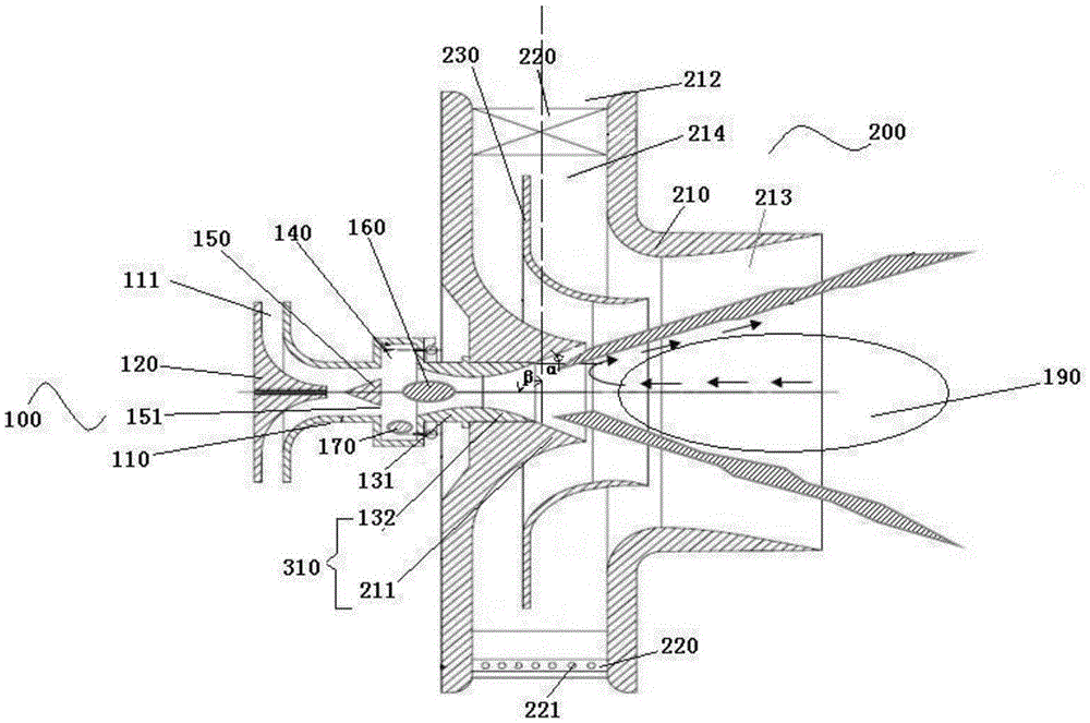
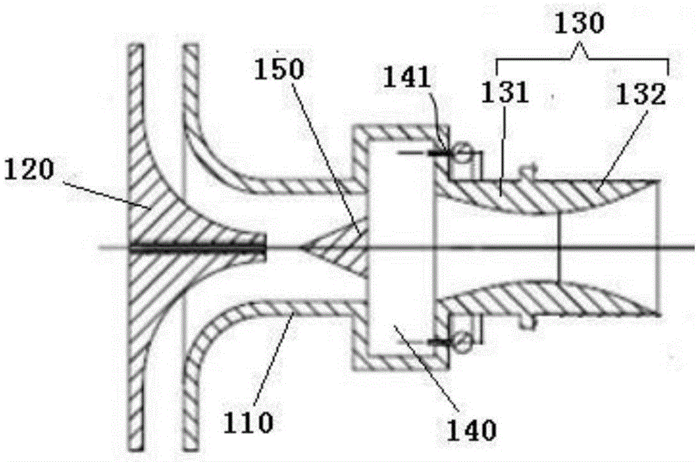
[0060] Such as figure 2 and image 3 As shown, the difference between this embodiment and Embodiment 1 is that the cavity fuel port and the cavity air inlet 141 are both arranged on the side of the cavity 140 close to the flame control pipe 130, that is, the rear edge of the cavity 140, The equivalence ratio of fuel to air in cavity 140 is the actual fuel to air ratio divided by the fuel to air ratio for complete combustion; the equivalence ratio of fuel to air in cavity 140 is 1.2 to 1.4; the actual fuel to air ratio is the cavity of cavity 140 The ratio of the fuel mass actually passed into the body fuel port and the air mass actually passed into the cavity air inlet 141; the fuel-air ratio of complete combustion is when the winding material is fully burned, the quality of the fuel used and the required The ratio of the mass of air. This ratio ensures that a rich fuel is formed in the cavity 140 . The fuel is introduced from the fuel ring pipe arranged on the concave cav...


PUM


Abstract

The invention provides a combustor for a gas turbine and a flame combustion method. The combustor comprises a central on-duty combustor and a main premix combustor which are connected with each other, wherein the central on-duty combustor comprises an on-duty combustor body; the on-duty combustor body is provided with a central on-duty nozzle; a gas outlet of the on-duty combustor body is provided with a flame control pipeline; the inner wall of the flame control pipeline is an inwardly bulging cambered structure; a concave cavity is arranged along the circumferential direction of the inner wall of the on-duty combustor body; the concave cavity is positioned between the central on-duty nozzle and flame control pipeline, and is provided with a cavity fuel port and a cavity gas inlet; a central blunt body is arranged inside the on-duty combustor body; the central blunt body is positioned between the central on-duty nozzle and concave cavity; a blunt body ventilation clearance is arranged between the central blunt body and the inner wall of the on-duty combustor body; and the blunt body ventilation clearance communicates with the concave cavity. The on-duty flame and main premix flame are positioned in different regions, thereby avoiding the interaction between the two flames, and enhancing the combustion stability.

Description

technical field [0001] The invention relates to the technical field of gas turbine combustion chambers, in particular to a burner and a flame combustion method for a gas turbine. Background technique [0002] Currently, lean premix combustors using dry low-pollution and dry low-NOx emission combustion technologies all use diffusion or partial premix duty nozzles. Stabilize the small flame or use a blunt body and other flame-stabilizing structures to stabilize the combustion of the premixed main flame. The formation of a stable small flame through the diffusion center duty nozzle is a hot technology in early heavy gas turbines. The problem it faces is that the temperature of the diffusion combustion flame is high, resulting in more NOx emissions. Partial premix duty design can reduce NOx emissions, but it has problems such as combustion stability and backfire. In addition, the duty stage and the premix stage are graded but not partitioned, which easily couples the uniformly...

Claims


Application Information

Patent Timeline
IPC IPC(8): F23R3/38F23R3/58
CPCF23R3/38F23R3/58F23R2900/00002
Inventor 高贤智谈芦益何磊
Owner SHANGHAI ELECTRIC GAS TURBINE CO LTD
Learn More