Finned heat exchange tube

A technology of heat exchange tubes and fins, which is applied in the field of vaporizers, can solve the problem that the fin heat exchange tubes and the fin heat exchange tubes cannot be installed with connecting pieces, the installation stability of the fin heat exchange tubes is poor, and the overall heat transfer efficiency is low. problem, to achieve the effect of simple structure, consistent thermal expansion, and stable connection

Inactive Publication Date: 2016-05-25
WUXI PHAETON CRYOTECH CO LTD
View PDF0 Cites 0 Cited by
  • Summary
  • Abstract
  • Description
  • Claims
  • Application Information

AI Technical Summary

Problems solved by technology

[0002] At present, the working process of the finned heat exchange tubes of the existing air-bath evaporator is that the low-temperature liquid medium flows into the tube wall and the fins outside the tube wall for heat exchange. The original overall heat transfer efficiency is not high. After the wall has dirt, the heat transfer efficiency will be reduced. At the same time, the fin structure of the existing finned heat exchange tube is single, which cannot meet the problem of installing connecting pieces between the finned heat exchange tube and the finned heat exchange tube. Therefore, each fin Poor installation stability of heat exchange tube

Method used


Image

  • Finned heat exchange tube
  • Finned heat exchange tube

Examples


Embodiment Construction

[0015] The specific embodiments of the present invention will be described below with reference to the accompanying drawings.

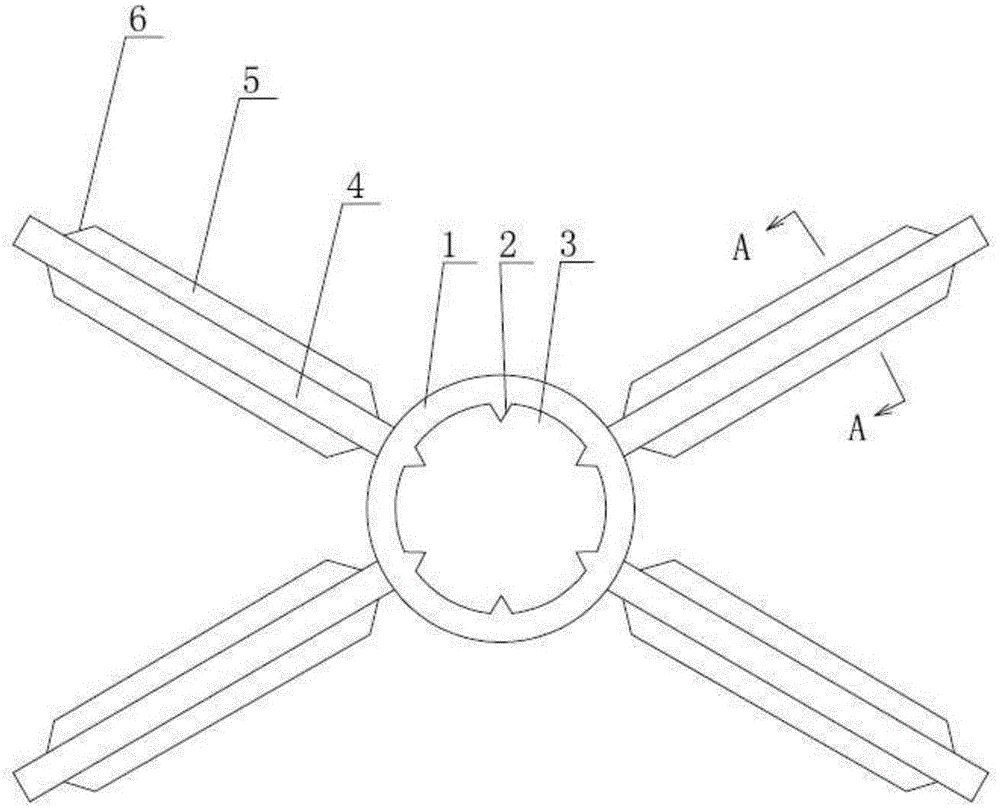
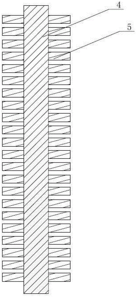
[0016] like figure 1 , figure 2 As shown, the finned heat exchange tube includes a tube body 1 with an inner hole, the tube body 1 is made of an aluminum alloy material, and a plurality of tapered portions 2 are formed on the inner hole wall of the tube body 1 along the circumferential direction, each tapered portion 2 A semicircular groove 3 is formed therebetween; a plurality of fins 4 are also arranged on the outer circumference of the tube body 1 , and a plurality of thermally conductive sheets 5 are respectively connected to both sides of the fins 5 . The tapered portions 2 are evenly arranged with the center of the tube body 1 as the center. The fins 4 are connected with the tube body 1 to form an "X" shape. The adjacent heat-conducting sheets 5 are arranged in parallel with each other, and the top and bottom surfaces of the heat-conducting ...


PUM


Abstract

The invention relates to a finned heat exchange tube which comprises a tube body with an inner hole, wherein a plurality of conic parts are formed in the inner hole wall of the tube body in the peripheral direction in an extending manner; a semicircular groove is formed between every two adjacent conic parts; a plurality of fins are arranged on the periphery of the tube body; a plurality of heat conducting strips are connected with both sides of each fin. According to the finned heat exchange tube, the structure is simple, the use is convenient, as the conic parts are arranged in the tube body, residual dirt in a tube medium can slip out along the surfaces of the conic parts, therefore reasonable and smooth flowing of the heat exchange medium is realized, highly efficient and rapid heat exchange is realized, and the heat exchange efficiency, owing to the arrangement of the heat conducting strips, is also improved; moreover, the fins are in seamless contact with the heat conducting strips, the heat conduction radiating area is large, resistances to thermal shock, mechanical vibration and thermal expansion are in consistency; besides, the heat conducting strips are provided with inclined planes so as to be easily connected with connecting strips, so that the finned heat exchange tube can be connected with the connecting strips more stably.

Description

technical field [0001] The present invention relates to the field of vaporizers, in particular to finned heat exchange tubes used in vaporizers. Background technique [0002] At present, the working process of the finned heat exchange tube of the existing air-bath vaporizer is that the low-temperature liquid medium flows into the tube wall and the fins outside the tube wall for heat exchange, and the original overall heat transfer efficiency is not high. After the wall is dirty, the heat transfer efficiency will be reduced. At the same time, the fin structure of the existing finned heat exchange tube is single, which cannot meet the problem of installing connecting pieces between the finned heat exchange tube and the finned heat exchange tube. The heat exchange tube installation stability is poor. SUMMARY OF THE INVENTION [0003] In view of the above-mentioned existing problems, the applicant has carried out research and improvement to provide a finned heat exchange tube...

Claims


Application Information

Patent Timeline
Patent Type & Authority Applications(China)
IPC IPC(8): F28F1/06F28F13/04F28F1/30F28F19/00
CPCF28F1/06F28F1/30F28F13/04F28F19/00
Inventor 俞军
Owner WUXI PHAETON CRYOTECH CO LTD
Why Eureka
Try Eureka