Spreading blade support structure on a spreading machine

A supporting structure and spreading machine technology, applied in the direction of spreading thin soft materials, thin material handling, transportation and packaging, etc., can solve the problems of unstable movement of spreading blades, short service life, increased wear, etc., to reduce The effect of after-sales service cost, improvement of production efficiency, and reduction of assembly man-hours

Active Publication Date: 2021-02-09
BULLMER ELECTROMECHANICAL TECH
View PDF7 Cites 0 Cited by
  • Summary
  • Abstract
  • Description
  • Claims
  • Application Information

AI Technical Summary

Problems solved by technology

[0002] Cloth spreading machine (also known as spreading machine) is a common equipment in garment factories. It can spread the rolled cloth on the machine table, and then use other machines to reprocess the flat cloth. When laying knitted fabrics on a cloth machine, it is necessary to unfold the folded fabrics to both sides without tension, and when the spreading blades move horizontally, they need a carrier to support their weight and guide their movement. In the existing structure, a pulley is used on two It is realized by sliding between thin shafts. The pulley is a grooved wheel, which is vertically limited by the two edges of the groove, and horizontally limited by the diameter of the groove. This structure has the following defects: 1. Between the pulley and the thin shaft Continuous friction between the pulleys will be very easy to wear, and eventually the blades will fall; 2. There is a gap between the pulley and the thin shaft, which will produce a lot of noise during continuous movement; 3. Black powder will be produced during the wear of the pulley. During the rotation of the spreading drum, the powder will be thrown onto the fabric, causing pollution to the fabric
[0004] The spreading roller device in the above patent document is not easy to assemble, and the slider will wear after sliding on the guide post for a long time at high frequency, resulting in an excessively large matching gap between the two, unstable movement of the spreading blade, and aggravated wear, which in turn leads to short service life

Method used


Image

  • Spreading blade support structure on a spreading machine
  • Spreading blade support structure on a spreading machine

Examples


Embodiment Construction

[0022] The following are specific embodiments of the present invention and in conjunction with the accompanying drawings, the technical solutions of the present invention are further described, but the present invention is not limited to these embodiments.

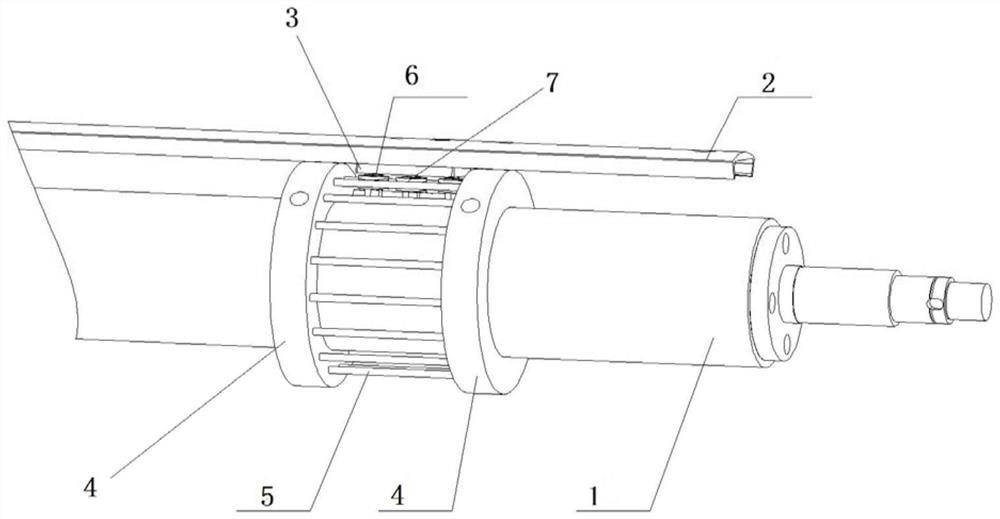
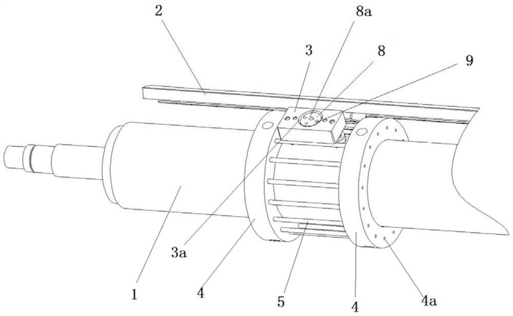
[0023] Such as figure 1 and figure 2 As shown, the spreading machine includes a spreading drum 1 and a spreading blade 2, and the supporting structure of the spreading blade includes a slider 3 and two fixed discs 4 set on the spreading drum 1 at parallel intervals, and the two fixed discs 4 is fixedly connected with the spreading drum 1, and several fixed thin rods 5 are arranged at intervals along the circumferential direction of the fixing plates 4 between the two fixed plates 4; the spreading blade 2 is fixed on one side of the slider 3, and the The other side is provided with at least one centering roller 6 and at least one eccentric roller 7, the slider 3 is located between two adjacent fixed thin rods 5, and the p...


PUM


Abstract

The invention provides a spreading blade support structure on a spreading machine, which belongs to the technical field of spreading machines. The utility model solves the technical problems such as the easy wear and tear of the supporting structure of the spreading blades on the existing spreading machine. The spreading machine includes a spreading drum and a spreading blade. The supporting structure of the spreading blade includes a slider and two fixed plates set on the spreading drum in parallel at intervals. The two fixed plates are arranged at intervals along the circumferential direction of the fixed plate. There are several fixed thin rods; the spreading blade is fixed on one side of the slider, and the other side of the slider is provided with at least one positive roller and at least one eccentric roller, and the slider is located between two adjacent fixed thin rods , the circumferential surface of the centered roller rolls against one of the fixed thin rods, and the circumferential surface of the eccentric roller rolls against the adjacent fixed thin rod; the slider is also equipped with an eccentric roller that can adjust the position of the eccentric roller. Regulator. The spreading blade support structure in the present invention operates stably and reliably, and has a long service life.

Description

technical field [0001] The invention belongs to the technical field of spreading machines, and relates to a spreading blade support structure on the spreading machine. Background technique [0002] Cloth spreading machine (also known as spreading machine) is a common equipment in garment factories. It can spread the rolled cloth on the machine table, and then use other machines to reprocess the flat cloth. When laying knitted fabrics on a cloth machine, it is necessary to unfold the folded fabrics to both sides without tension, and when the spreading blades move horizontally, they need a carrier to support their weight and guide their movement. In the existing structure, a pulley is used on two It is realized by sliding between thin shafts. The pulley is a grooved wheel, which is vertically limited by the two edges of the groove, and horizontally limited by the diameter of the groove. This structure has the following defects: 1. Between the pulley and the thin shaft Continu...

Claims


Application Information

Patent Timeline
Patent Type & Authority Patents(China)
IPC IPC(8): B65H47/00
Inventor 何贤安
Owner BULLMER ELECTROMECHANICAL TECH
Why Eureka
Try Eureka