Glass thickness detection apparatus and glass thickness detection method

A glass thickness and detection device technology, applied in the field of optical measurement, can solve the problems of difficulty in accurately controlling the relative position, affecting the measurement accuracy, limiting the use range of the detection device, etc., to achieve the effect of improving the accuracy and reducing the error

Inactive Publication Date: 2016-05-25
BEIJING AOPTEK SCI +1
View PDF8 Cites 2 Cited by
  • Summary
  • Abstract
  • Description
  • Claims
  • Application Information

AI Technical Summary

Problems solved by technology

Although this method uses two lasers for measurement, its measurement principle is based on the refraction of light
In the equipment and detection method provided in this patent, the laser and the CCD detector are located on both sides of the glass to be tested, and it is difficult to accurately control the relative position between the laser and the CCD detector and between the two and the glass to be tested. The CCD detector is not parallel to the surface of the glass to be tested, which affects the measurement accuracy
And, because this method needs glass to be placed in the detection device, therefore, limit the scope of use of this detection device

Method used


Image

  • Glass thickness detection apparatus and glass thickness detection method
  • Glass thickness detection apparatus and glass thickness detection method
  • Glass thickness detection apparatus and glass thickness detection method

Examples


Embodiment Construction

[0034] In the following description, for illustrative purposes, many specific details are set forth in order to provide a comprehensive understanding of one or more embodiments. However, it is obvious that these embodiments can also be implemented without these specific details. In other examples, for the convenience of describing one or more embodiments, well-known structures and devices are shown in the form of block diagrams.

[0035] Hereinafter, various embodiments according to the present invention will be described in detail with reference to the accompanying drawings.

[0036] Figure 4 It is a schematic diagram showing the structure of the glass thickness detection device according to the present invention. Such as Figure 4 As shown, the glass thickness detection device related to the present invention includes: a housing 400 for accommodating various components of the glass thickness inspection device, and has a bottom surface 405 that can contact the surface of the gla...


PUM


Abstract

The invention provides a glass thickness detection apparatus. The apparatus comprises a shell, two light sources, a photoelectric detection portion and a glass thickness calculation portion, wherein the shell possesses a bottom surface portion which can be contacted with a detected glass surface, and the bottom surface portion is in a plane shape and light can pass through the bottom surface portion; the two light sources are oppositely arranged in the shell with a prescribed space and can emit light which is used for detection and is shot to the bottom surface portion; the photoelectric detection portion is formed by a plurality of photoelectric detection units which are arranged, is arranged in the shell and can receive reflected light from the detected glass; and the glass thickness calculation portion calculates a thickness parameter of the detected glass according to detection information output by the photoelectric detection portion. According to the structure, precision of glass thickness measurement is increased and thickness measurement precision of glass with a wedge angle is especially improved.

Description

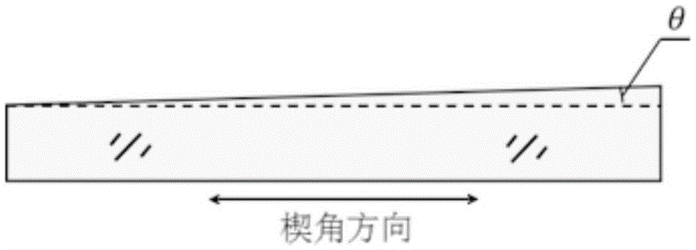
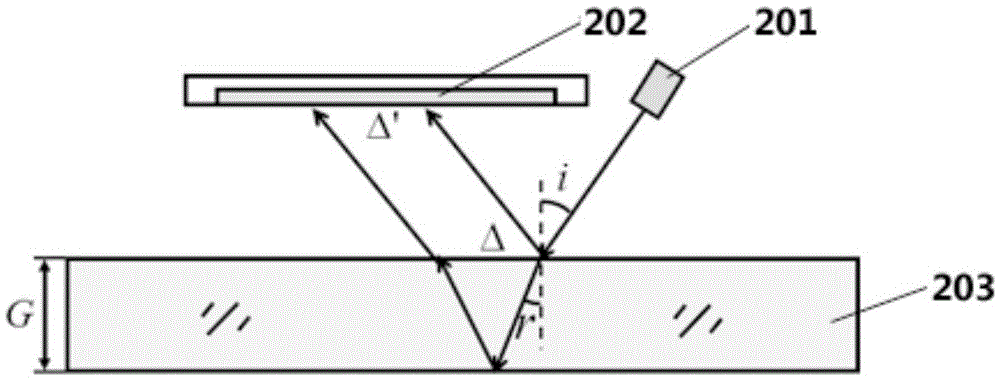
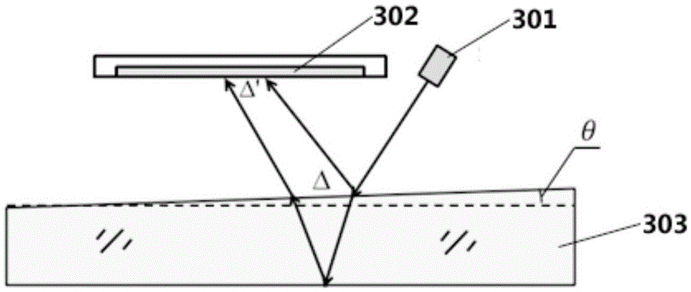
Technical field [0001] The invention relates to the technical field of optical measurement, and more specifically, to a glass thickness detection device and method. Background technique [0002] At present, the optical measurement method is mainly used to measure the thickness of glass. The optical measurement method not only has high accuracy, but also can realize non-contact measurement. The existing optical measurement methods for measuring glass thickness mainly use the principle of light refraction and reflection. A beam of light is obliquely incident on the glass to be measured. The light beam after the glass refraction is received by the photodiode sensor, and the computer or The single-chip microcomputer performs calculations to obtain the glass thickness value. For example, the patent application number CN200920201105 discloses a glass thickness measuring instrument, the patent application number CN201010528877 discloses a hollow glass thickness and aluminum frame width...

Claims


Application Information

Patent Timeline
IPC IPC(8): G01B11/06
Inventor 黄达泉常俏吴筱张鑫钟星辉
Owner BEIJING AOPTEK SCI
Why Eureka
Try Eureka