PWM-wave-controlled electromagnetic relay driving circuit and implementation method

An electromagnetic relay and drive circuit technology, applied in relays, circuits, electrical components, etc., can solve the problems of long arcing time, contact bounce, electromagnetic relay failure, etc., and achieve safe and stable operation, cost saving, and simple structure. Effect

Active Publication Date: 2016-05-25
NANJING SCIYON DRIVE TECH
View PDF3 Cites 20 Cited by
  • Summary
  • Abstract
  • Description
  • Claims
  • Application Information

AI Technical Summary

Problems solved by technology

[0003] In the field of frequency conversion, for the drive of electromagnetic relays, such as figure 1 This kind of circuit has simple structure and low cost, but it has many disadvantages for the control of electromagnetic relay: on the one hand, the electromagnetic relay of this driving circuit must match the power supply voltage, that is to say, the voltage of this electromagnetic relay must match the power supply voltage Only when they are basically equal can they be driven normally
However, the operating voltage in the field of inverters is generally 15V to 18V, and the rated voltage of electromagnetic relays is generally 12V or 24V, which do not match the operating voltage.
[0004] If the actual applied coil voltage is too low, it may cause the electromagnetic relay to fail without action. Even if it can operate, due to the low coil voltage, the magnetic force generated by the coil is relatively small, and the electromagnetic relay operates slowly, resulting in a relatively long burning arc time. It will accelerate the failure of the electromagnetic relay; if the applied coil voltage is too high, it will cause the coil of the electromagnetic relay to heat up relatively high. It will melt, burn out and fail. Even if it is not burned, due to the high coil voltage, the magnetic force generated is relatively large and the action is fast, so the kinetic energy generated needs to be released through elastic enabling, so the contacts of the electromagnetic relay will bounce back for a long time. Accelerating the Failure of Electromagnetic Relays
[0005] In view of the above problems, the existing technologies mainly include the following solutions: one is to add a 12V or 24V output to the transformer to drive an electromagnetic relay with a rated voltage of 12V or 24V; The working voltage is boosted from 15V to 18V to 24V to drive an electromagnetic relay with a rated voltage of 24V; the third is to add a step-down circuit to step down the working voltage from 15V to 18V to 12V to drive an electromagnetic relay with a rated voltage of 12V. Relay, these three schemes undoubtedly increase the cost of the electromagnetic relay drive circuit

Method used


Image

  • PWM-wave-controlled electromagnetic relay driving circuit and implementation method
  • PWM-wave-controlled electromagnetic relay driving circuit and implementation method
  • PWM-wave-controlled electromagnetic relay driving circuit and implementation method

Examples


Embodiment Construction

[0037] The present invention will be described in detail below in conjunction with the accompanying drawings.

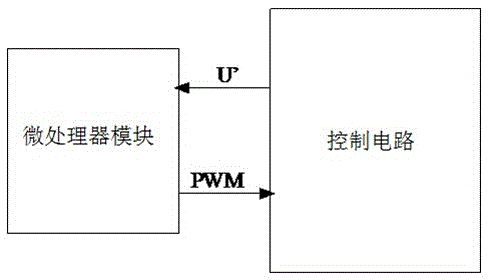
[0038] figure 2 It is a structural block diagram of an electromagnetic relay drive circuit controlled by PWM waves disclosed by the present invention, including a microprocessor module and a control circuit.

[0039] Wherein: the microprocessor module is a circuit module including a microprocessor (MCU) of a central processing unit (CPU), a digital signal processor (DSP), a complex programmable logic device (CPLD) or a programmable controller (PLC);

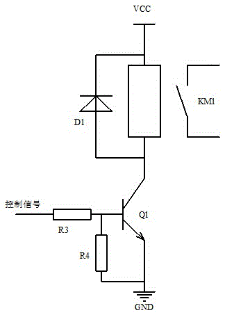
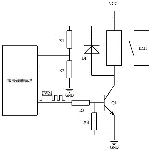
[0040] combine image 3 , The control circuit includes a drive circuit power supply VCC, a freewheeling diode D1, an electromagnetic relay KM1, a triode Q1, a resistor R1, a resistor R2, a resistor R3, and a resistor R4. The relationship between each composition is: one end of the resistance R1 is connected to the power supply VCC of the electromagnetic relay drive circuit, the other end is connected to the resistanc...


PUM


Abstract

The invention discloses a PWM-wave-controlled electromagnetic relay driving circuit and an implementation method. The electromagnetic relay driving circuit comprises a microprocessor module and a control circuit, wherein the control circuit comprises a driving circuit power supply, an electromagnetic relay, a freewheel diode, a triode and resistors, wherein both ends of a main contact coil of the electromagnetic relay are connected with the freewheel diode in parallel, a negative electrode of the freewheel diode is connected with the driving circuit power supply, a positive electrode of the freewheel diode is connected with a collector of the triode, the driving circuit power supply is subjected to voltage division through the resistors and connected to an A/D port of the microprocessor module, a PWM wave generated by an I/O port of the microprocessor module controls a base of the triode, and an emitter of the triode is grounded through one of the resistors. The PWM-wave-controlled electromagnetic relay driving circuit is simple in structure, saves cost, is fast in operation of the electromagnetic relay, and ensures safe and stable operation.

Description

technical field [0001] The invention belongs to the field of industrial automation frequency converters, and relates to a 12V electromagnetic relay drive circuit, in particular to a PWM wave-controlled electromagnetic relay drive circuit and its implementation method Background technique [0002] The frequency converter is a power control device that uses the on-off function of power semiconductor devices to convert the power frequency power supply into another frequency. / overvoltage / overload protection and other functions. [0003] In the field of frequency conversion, for the drive of electromagnetic relays, such as figure 1 This kind of circuit has simple structure and low cost, but it has many disadvantages for the control of electromagnetic relay: on the one hand, the electromagnetic relay of this driving circuit must match the power supply voltage, that is to say, the voltage of this electromagnetic relay must match the power supply voltage Only when they are basica...

Claims


Application Information

Patent Timeline
Patent Type & Authority Applications(China)
IPC IPC(8): H01H47/02
CPCH01H47/02
Inventor 沈德明张弦裴超陈小龙
Owner NANJING SCIYON DRIVE TECH
Why Eureka
Try Eureka