Electric pump

An electric pump, electric motor technology, applied in the direction of electric motor control, pump, pump device, etc., to achieve the effect of increasing the manufacturing cost

Inactive Publication Date: 2016-05-25
TBK
View PDF8 Cites 6 Cited by
  • Summary
  • Abstract
  • Description
  • Claims
  • Application Information

AI Technical Summary

Problems solved by technology

However, there is the following problem: the rotor is immersed in the liquid leaked into the housing, so if the liquid viscosity is high when the liquid temperature is low, and the driving resistance due to the liquid viscosity is larger than the rotational driving force of the rotor, it is difficult to communicate with the stator. The energization control of the coil drives the rotor to rotate accordingly

Method used


Image

  • Electric pump
  • Electric pump
  • Electric pump

Examples


Embodiment Construction

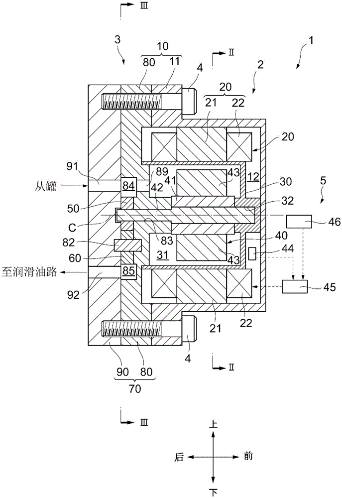
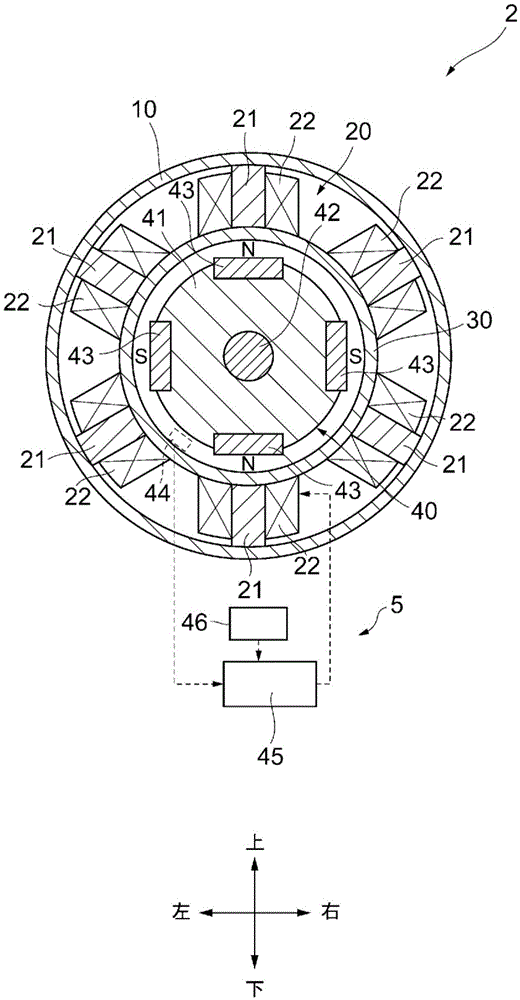
[0023] Hereinafter, embodiments of the present invention will be described with reference to the drawings. exist figure 1 2 shows a cross-sectional view of an electric oil pump 1 as an example to which the present invention is applied. First, refer to this figure 1 The overall structure of the electric oil pump 1 will be described. In addition, in the embodiments described below, for convenience of description, front and rear, left and right (indicated by arrows attached to each figure) are used to define figure 1 The arrow is not shown in , but it is a direction perpendicular to the paper surface) and up and down will be described. In addition, in the present embodiment, an electric oil pump 1 is exemplified that sucks lubricating oil stored in a tank provided in a vehicle (for example, an engine oil pan) and discharges it to lubricating oil passages connected to various parts of the engine.

[0024] The electric oil pump 1 is configured to include: an AC-type electric ...


PUM


Abstract

An electric oil pump (1) constructed by integrally combining an electric motor (2) with an oil pump (3), wherein: the electric motor is composed of a motor casing (10), a drive shaft (42) that is disposed in a motor housing chamber (12) formed inside the motor casing and is roratably supported, a rotor (40) that is disposed on the drive shaft, and a stator (20) that is located inside the motor housing chamber and is attached to the motor housing; the electric oil pump is equipped with an internal controller (45) that controls application of electric power to the stator so as to cause the drive shaft to be driven to rotate via the rotor; and the internal controller is equipped with a normal mode for controlling application of electric power to the stator such that the drive shaft rotates in accordance with an externally input rotation command and a heat generation mode for controlling application of electric power to the stator such that the stator generates heat at a higher heating efficiency than the heating efficiency of the stator when the application of electric power is controlled in the normal mode.

Description

technical field [0001] The present invention relates to an electric pump composed of an electric motor that drives a rotor and a stator to rotate in a non-contact manner and a liquid pump. Background technique [0002] As such an electric pump, the electric pump described in patent document 1 is known, for example. In this electric pump, a rotor 5 is accommodated inside a housing (partition member) 2 , and a stator core 8 and a stator coil 9 (stator) are arranged outside the housing 2 . The housing 2 is provided to prevent the liquid sucked and discharged by the liquid pump from entering the electric motor through the gap between the drive shaft and the casing, and this electric pump is called a canned pump. [0003] Patent Document 1: Japanese Patent Laid-Open No. 2001-280284 Contents of the invention [0004] The problem to be solved by the invention [0005] The rotor of the electric pump is provided with, for example, a permanent magnet, whereby the rotor is rotate...

Claims


Application Information

Patent Timeline
IPC IPC(8): F04B15/02F04B17/03F04D13/06F04B49/06F04B53/08F04C13/00F04C15/00F04D29/58H02P6/00
CPCH02P6/00F04B15/02F04B17/03F04B49/065F04B53/08F04C13/004F04D13/0606F04D29/588F04C2/18F04C15/008F04C15/0096F04C2270/46F04C2270/86F04C2210/44F04C2270/19H02P29/62F05B2210/11F05D2210/11F04C13/001
Inventor 冈本和晃吉谷浩忠
Owner TBK
Why Eureka
Try Eureka