Snake climbing prevention device of power transmission pole

A technology for power transmission poles and anti-snakes, which is applied in animal repellents, buildings, building types, etc., can solve the problems of snake death and inability to protect the ecological environment, and achieves a simple production process, a strong and reliable support body, and is not afraid of wind and sun. The effect of sun and rain

Inactive Publication Date: 2016-06-01
方家耀
View PDF9 Cites 6 Cited by
  • Summary
  • Abstract
  • Description
  • Claims
  • Application Information

AI Technical Summary

Problems solved by technology

The publication number is CN104319716A, and the Chinese patent document published on January 28, 2015 discloses an anti-snake fitting, including a body structure and a hook fastening structure. Arm, on each fixed arm of the body structure, M8 nuts, platen supports, platen fixtures and threading sets are fixed in turn, and the end of the M6 ​​bolts close to the platen supports is provided with an M6 bolt platen, and the tool is installed on the M6 ​​bolt plate and Between the support parts of the pressure plate, the hook fastening structure includes M8 bolts and M8 nuts. One end of the M8 bolt is an M8 invisible nut, and the other end is a fixed catch. The anti-snake fittings are fixed by the M8 bolts, M8 nuts and fixed catches. On the electric tower, the snakes are prevented from climbing the electric tower by knives. In this structure, knives are still used to prevent snakes from crawling, which is easy to cause snake death and cannot protect the normal ecological environment.

Method used


Image

  • Snake climbing prevention device of power transmission pole
  • Snake climbing prevention device of power transmission pole
  • Snake climbing prevention device of power transmission pole

Examples


Embodiment Construction

[0023] Embodiments of the present invention will be described in detail below in conjunction with the accompanying drawings.

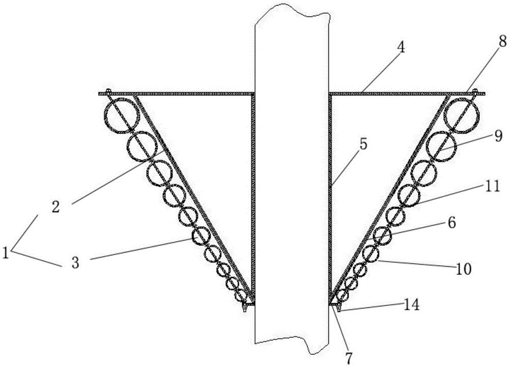
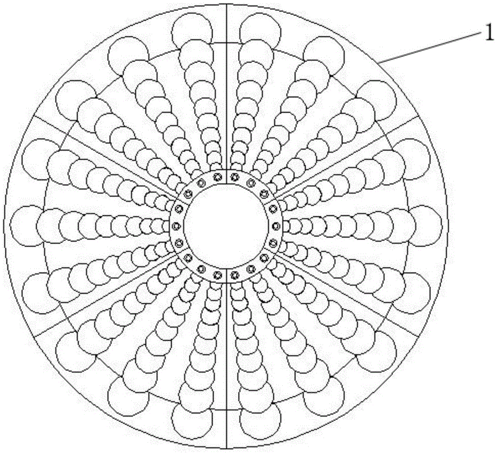
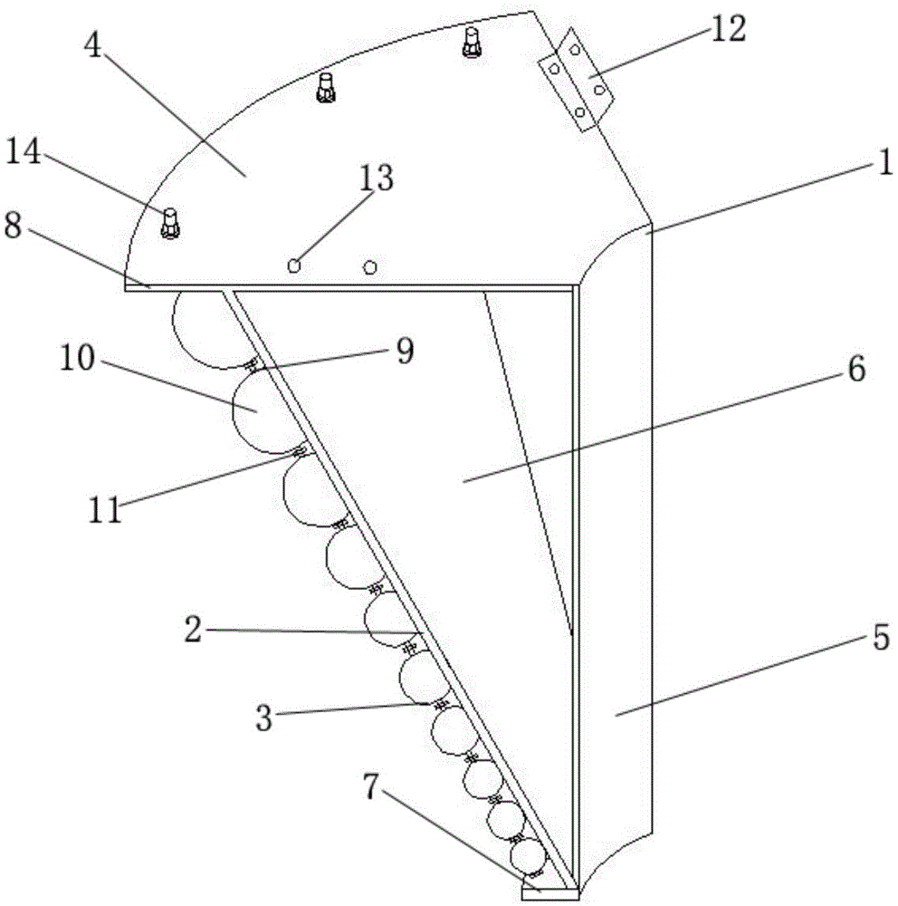
[0024] Such as Figure 1 to Figure 3 The transmission pole anti-snake climbing device of the present invention shown in , is spliced ​​by several anti-snake climbing module units 1 along the circumferential direction to form a frustum-shaped structure with an inner hole, and the inner hole can be designed according to the actual size of the transmission pole, as shown in Fig. Shown in is a circular inner hole, which is formed by splicing six anti-snake climbing module units 1. The device is assembled on the transmission pole. The anti-snake climbing module unit 1 includes a bracket body 2 and a ball string 3 . The support body 2 includes an upper plate 4, an inner hole wall plate 5 and an outer wall plate 6, and the upper plate 4, the inner hole wall plate 5 and the outer wall plate 6 are connected end to end to form a support body 2 whose longitudina...


PUM


Abstract

The invention discloses a snake climbing prevention device of a power transmission pole. A frustum-shaped structure with an inner hole is formed by splicing a plurality of snake climbing prevention module units in the circumferential direction. Each snake climbing prevention module unit comprises a support body and ball strands, wherein the support body comprises an upper plate, an inner hole wall plate and an outer wall plate, the upper plate, the inner hole wall plate and the outer wall plate are connected with one another end to end to form the support body with the reversed-right-triangle-shaped vertical section, the bottom end of the support body extends outwards to be provided with a lower positioning plate, the upper plate extends outwards to be provided with an upper positioning plate matched with the lower positioning plate, and the ball strands are arranged between the upper positioning plate and the lower positioning plate in parallel and at intervals in the length direction of the outer wall plate with the interval distance kept. Each ball strand comprises a connection rod, balls and partition gaskets, wherein the balls with the diameters gradually increased are connected to the connection rod in a penetrating mode in sequence, and the partition gaskets are arranged between the adjacent balls. By means of the device, snakes can be effectively prevented from climbing the transmission rod without being killed, and the natural ecological environment is maintained.

Description

technical field [0001] The invention relates to the technical field of electric equipment, in particular to an anti-snake climbing device for transmission poles. Background technique [0002] During the peak period of bird breeding, nests are often built on the poles of overhead lines to lure snakes to crawl to the top of the poles to eat bird eggs. When snakes approach or even touch the transmission lines, it will cause a short circuit of the transmission lines and cause large-scale power outages , which seriously threatens the safe operation of the power grid. In order to ensure the safe operation of the power grid, measures need to be taken to prevent snakes from crawling along the pole frame to the top. The announcement number is CN201608485U, and the announcement date is October 13, 2010. In the Chinese patent document, a power supply line anti-snake device is disclosed, which is composed of acupuncture, fixing clips, and connecting bodies. The center of the circular ...

Claims


Application Information

Patent Timeline
IPC IPC(8): A01M29/30E04H12/00
CPCA01M29/30E04H12/00
Inventor 方家耀
Owner 方家耀
Why Eureka
Try Eureka