Pipe blanking equipment

A technology for pipes and equipment, applied in the field of pipe blanking equipment, can solve the problems of high production cost, troublesome programming, cumbersome control, etc., and achieve the effects of low cost, compact processing procedure and improved processing efficiency

Inactive Publication Date: 2016-06-01
SHANDONG UNIV OF SCI & TECH
View PDF7 Cites 15 Cited by
  • Summary
  • Abstract
  • Description
  • Claims
  • Application Information

AI Technical Summary

Problems solved by technology

Although the cutting machine can be equipped with a control unit according to the needs, and realize the cutting of the pipe through the detection of multiple position sensors, its structure is complex, the control is cumbersome, and the programming in the control process is also cumbersome, and the production cost is high

Method used


Image

  • Pipe blanking equipment
  • Pipe blanking equipment
  • Pipe blanking equipment

Examples


Embodiment Construction

[0026] The present invention will be further described in detail below in conjunction with the accompanying drawings and specific embodiments, but the present invention is not limited to these embodiments.

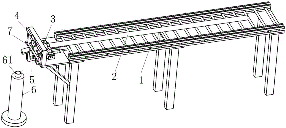
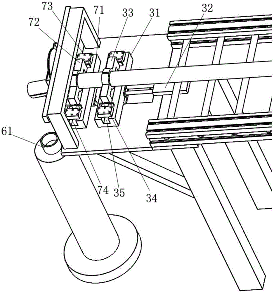
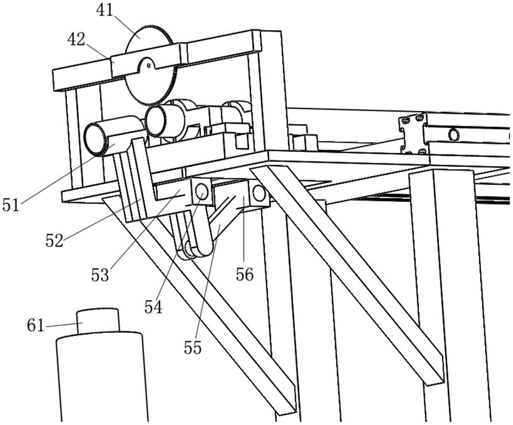
[0027] Such as Figure 1 to Figure 3 As shown, the pipe blanking equipment includes a pipe support bracket 1, and one side of the pipe support bracket 1 is provided with a pipe conveying device and a pipe cutting device 4:

[0028] The pipe conveying device includes a retractable clamping and feeding mechanism 3, and the retractable clamping and feeding mechanism 3 includes a moving slider 31, a driving part that drives the moving slider 31 to move axially along the pipe 2, and is arranged on the moving slider 31 and The first clamping manipulator that clamps and releases the pipe material 2; each time the moving slider 31 moves once, its action stroke is equal to the length of each section of pipe material that needs to be cut, and the moving slider 31 is driven by the dr...


PUM


Abstract

The invention discloses pipe blanking equipment. The pipe blanking equipment comprises a pipe supporting frame, wherein a pipe conveying device and a pipe cutting device are arranged on one side of the pipe supporting frame, the pipe cutting device is suspended above a to-be-cut end of a to-be-cut pipe, the pipe conveying device comprises a telescopic clamping conveying mechanism, and the telescopic clamping conveying mechanism comprises a moving sliding block, a driving part for driving the moving sliding block to move in the axial direction of the pipe and a first clamping manipulator arranged on the moving sliding block and used for clamping and releasing the pipe. The pipe blanking equipment can realize even cutting, fixed-length cutting or head-and-tail cutting of the pipe and is high in automation degree, high in blanking speed and easy to control.

Description

technical field [0001] The invention relates to a material cutting device, in particular to a pipe material cutting device. Background technique [0002] The blanking equipment is an indispensable part in the operation of the automatic production line, and the blanking equipment directly affects the working rhythm of the automatic production line. The pipe cutting equipment is a device for cutting long pipes. The existing pipe cutting equipment, for the workflow of the pipe cutting, is set at the front end of the frame by setting a stop at the position of the required length. Block, and then manually put one end of the pipe against the block to complete a section of cutting. If it is necessary to cut pipes of different lengths, it is necessary to manually set the position of the stopper again. This production method of manually adjusting the fixed length and cutting by manual feeding is particularly inefficient, and the fixed length method of manual setting and manual feedi...

Claims


Application Information

Patent Timeline
Patent Type & Authority Applications(China)
IPC IPC(8): B23D45/12B23D47/06B23D47/04
CPCB23D45/12B23D47/042B23D47/06
Inventor 王智伟刘毅王吉岱王峰
Owner SHANDONG UNIV OF SCI & TECH
Why Eureka
Try Eureka