Circular screen printer device with antiskid roller

A rotary screen printing and roller technology, applied in screen printing presses, printing presses, rotary printing presses, etc., can solve the problems of lifting the edges of both sides of the guide belt, slipping between the guide belt and the roller, affecting the appearance, etc. Solve the effect of easy to produce edge warping, smooth running of the guide belt, and ingenious design concept

Inactive Publication Date: 2016-06-01
SUZHOU HUACE TEXTILE SCI & TECH
View PDF5 Cites 2 Cited by
  • Summary
  • Abstract
  • Description
  • Claims
  • Application Information

AI Technical Summary

Problems solved by technology

[0003] However, in the prior art, the distance between the driving roller and the driven roller is mainly adjusted to increase the tension of the guide belt, so as to increase the friction between the guide belt and the roller, thereby reducing the slippage of the guide belt. However, this solution has the following defects: the more times the tension is adjusted, the shorter the service life of the guide belt will be, which will affect the subsequent use of the guide belt; manual corrections are required when adjusting the tension, which is time-consuming and laborious; and more After adjusting the tension for the first time, it is easy to increase the friction between the edge parts on both sides of the guide belt and the roller, causing the edge parts on both sides of the guide belt to warp, causing damage to the guide belt and affecting the appearance. It is easy to slip between the cylinders, and the cloth to be printed attached to the guide belt will slide with the guide belt, reducing the printing accuracy

Method used


Image

  • Circular screen printer device with antiskid roller
  • Circular screen printer device with antiskid roller
  • Circular screen printer device with antiskid roller

Examples


Embodiment Construction

[0020] In order to make the technical means, creative features, objectives and effects of the present invention easy to understand, the present invention will be further described below in conjunction with specific embodiments.

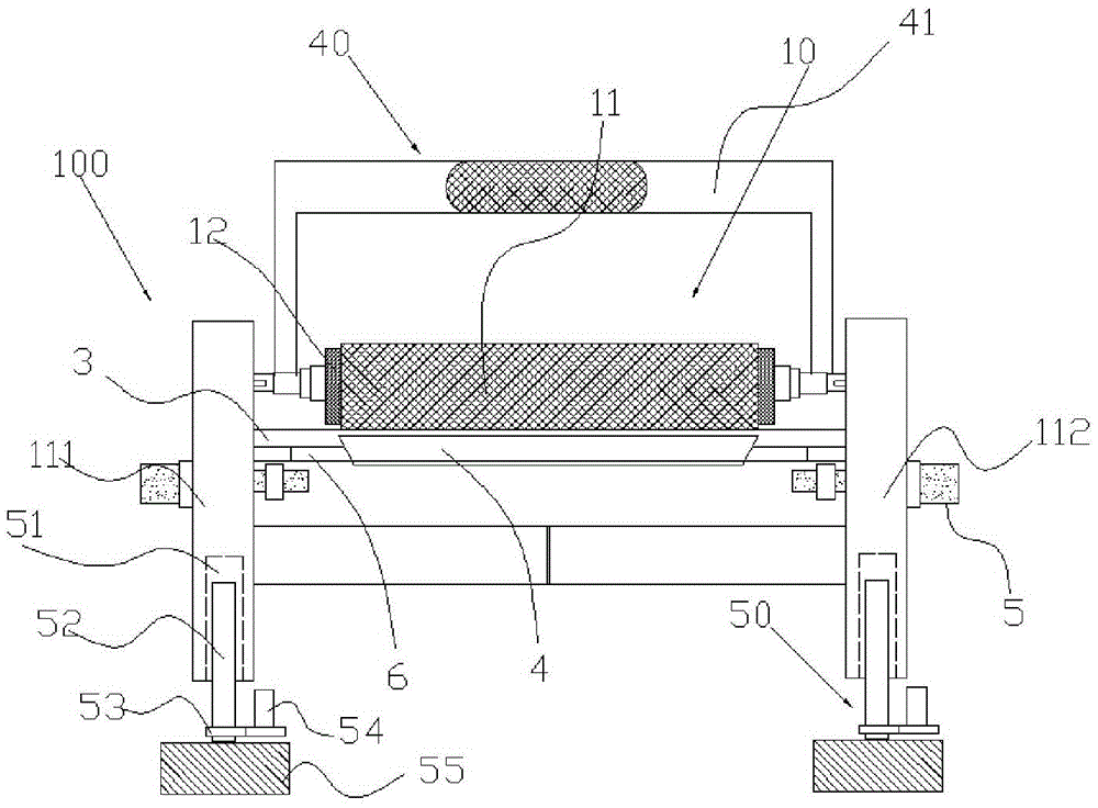
[0021] Such as Figure 1 to Figure 5 A rotary screen printing machine device with non-slip rollers is shown, including a rotary screen, a printing guide belt 3, etc., and is characterized in that it also includes a strip-shaped groove 4 arranged below the rotary screen and the printing guide belt, The outer sides of the two ends of the elongated groove 4 along the lengthwise direction are fixedly connected with a fixing frame 6, and the fixing frame 6 is fixed on the first column 111 and the second column 112 arranged vertically, and the first column 111 The roller printing device 10 is fixed on the second column 112, and the two ends of the roller printing device 10 are connected to the first column 111 and the second column 112 in a rotatable manner...


PUM


Abstract

The invention discloses a circular screen printer device with an antiskid roller. The circular screen printer device comprises a circular screen and a printing conduction band and further comprises a long-strip-shaped trough arranged below the circular screen and the printing conduction band. Fixed frames are fixedly connected to the outer sides of the two ends of the long-strip-shaped trough in the longitudinal direction correspondingly. The fixed frames are fixed to a first vertical pillar and a second vertical pillar which are vertically arranged correspondingly. A roller printing device is fixed to the first vertical pillar and the second vertical pillar. The two ends of the roller printing device are rotationally connected with the first vertical pillar and the second vertical pillar correspondingly. The roller printing device is of a step type. The two ends of the roller are each provided with a small segment of step. The diameter of the middle area segment of the roller is larger than that of the area segments of the two ends of the roller. An antiskid structure used for increasing friction force is arranged on the part, located in the milled area segment, of the outer surface of the roller. The antiskid structure is antiskid lines formed on the outer surface of the roller printing device. The circular screen printer device is simple and reasonable in structure and ingenious in design concept.

Description

Technical field: [0001] The invention relates to a rotary screen printing machine device with an anti-slip roller. Background technique: [0002] The rotary screen printing machine is a major equipment for textile printing. It mainly uses the rotary screen to perform pure rolling on the fabric, and then prints the slurry on the textile through scraping or magnetic bar devices, and forms certain patterns and colors. , so as to complete the entire printing process, the rotary screen printing machine and other units form a combined machine, which can be used for printing cotton fabrics, chemical fibers and their blended fabrics, general knitted fabrics, and silk fabrics. The applicable raw materials are: nylon multifilament yarn ), polypropylene filament yarn), polypropylene, polyester, nylon, PP, low elastic, high elastic, cotton yarn), pearl yarn, leather, mixed, etc. The rotary screen printing machine has reasonable structure, easy operation and high production efficiency, ...

Claims


Application Information

Patent Timeline
Patent Type & Authority Applications(China)
IPC IPC(8): B41F15/08B41F15/14
CPCB41F15/08B41F15/14
Inventor 陈永林
Owner SUZHOU HUACE TEXTILE SCI & TECH
Why Eureka
Try Eureka