Hydraulic type cantilever grain delivery machine

A storage machine, hydraulic technology, applied in the direction of conveyor, loading/unloading, transportation and packaging, etc., can solve the problems of complex equipment structure, safety performance needs to be improved, etc., to achieve simplified equipment structure, simple and convenient installation and maintenance, The effect of strong overload capacity

Active Publication Date: 2016-06-01
LIAONING HONGRUI TECH DEV
View PDF7 Cites 3 Cited by
  • Summary
  • Abstract
  • Description
  • Claims
  • Application Information

AI Technical Summary

Problems solved by technology

However, the motor and sprocket mechanism drive the cantilever screw conveyor shaft to rotate. It needs to be equipped with electric slip rings and anti-explosion treatment. The structure of the equipment is still complicated, and the safety performance still needs to be improved.

Method used


Image

  • Hydraulic type cantilever grain delivery machine

Examples


Embodiment Construction

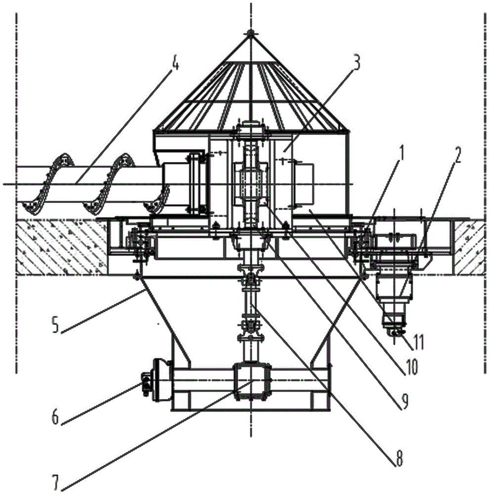
[0013] The specific embodiment of the present invention is described in conjunction with accompanying drawing:

[0014] Such as figure 1 , The hydraulic cantilever unloading machine includes a slewing support 1, the slewing support 1 is an external gear slewing support, and is arranged at the discharge port at the center of the bottom of the warehouse through a central mounting bracket. The slewing support 1 is equipped with a hydraulic slewing drive device 2, which is composed of a slewing drive hydraulic motor vertically fixed under the central mounting bracket and a drive gear installed on the output shaft of the slewing drive hydraulic motor. The drive gear It meshes with the external teeth of the slewing bearing 1. A main shaft seat frame 3 is fixedly installed above the rotating disk of the slewing bearing 1, and the main shaft seat frame 3 can adopt a box-shaped structure. The cantilever screw conveying shaft 4 is composed of a main shaft and a screw blade fixed on th...


PUM


Abstract

A hydraulic type cantilever grain delivery machine comprises a slewing bearing arranged on a discharge opening in the bottom of a silo and a hydraulic rotary drive device matched with the slewing bearing, a main shaft base frame is arranged on a rotating plate of the slewing bearing, a cantilever screw conveying shaft is installed through the main shaft base frame, a discharge hopper is arranged under a fixed ring of the slewing bearing, a hydraulic motor is arranged at the lower part of the discharge hopper and is connected to a worm through a right-angle reversing and speed-reducing machine and a universal coupling, the worm is vertically installed on the main shaft base frame, and a worm wheel meshed with the worm is arranged on the cantilever screw conveying shaft. According to the machine, the full-hydraulic drive structure is adopted, the advantages of hydraulic drive are given full play to, two power sources for revolution and autorotation of the cantilever screw conveying shaft are integrated, a hydraulic motor is externally and fixedly installed, and therefore the work performance and the efficiency of the grain delivery machine can be effectively improved, the structure can be simplified, the manufacturing cost can be lowered, the safety can be guaranteed, and pollution to delivered material can be avoided.

Description

technical field [0001] The invention relates to storage equipment for bulk materials, in particular to a hydraulic cantilever discharger suitable for discharging bulk granular and powdery materials from a flat-bottomed cylindrical silo. Background technique [0002] A prior patent application of the applicant with the application number CN201320706712.6 provides a cantilever unloading machine. The cantilever unloading machine adopts a cantilever-type screw conveying shaft and is driven The cantilever screw conveying shaft makes a revolution movement, and at the same time, the motor and the sprocket mechanism are used to drive the cantilever screw conveying shaft to rotate. Through the rotation and revolution of the cantilever screw conveying shaft, the materials in the warehouse are transported to the central discharge port for discharge. The cantilever bin-out machine is equipped with a screw out-out machine for driving a trolley relative to the end of the screw conveying s...

Claims


Application Information

Patent Timeline
Patent Type & Authority Applications(China)
IPC IPC(8): B65G65/46
CPCB65G65/466B65G2201/04B65G2201/042
Inventor 韩维娜周峰凌海明张海文
Owner LIAONING HONGRUI TECH DEV
Why Eureka
Try Eureka