Slag buffering system with flow control function

A flow control and buffer system technology, applied in the field of slag waste heat recovery, can solve the problems of high-quality slag waste heat resource waste, etc., and achieve the effect of continuous long-term operation, industrialization, and high safety prevention

Inactive Publication Date: 2016-06-01
XI AN JIAOTONG UNIV +1
View PDF4 Cites 24 Cited by
  • Summary
  • Abstract
  • Description
  • Claims
  • Application Information

AI Technical Summary

Problems solved by technology

[0004] The purpose of the present invention is to provide a slag buffer system with a flo

Method used


Image

  • Slag buffering system with flow control function
  • Slag buffering system with flow control function

Examples


Embodiment Construction

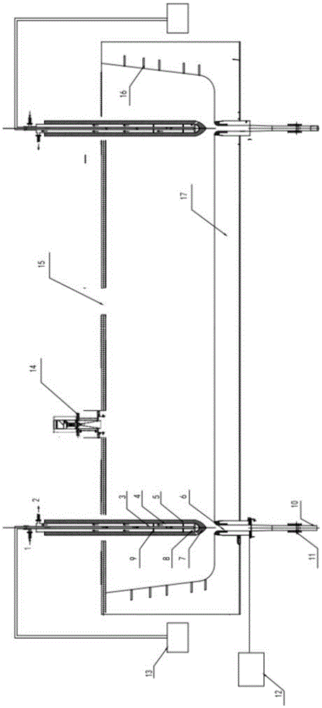
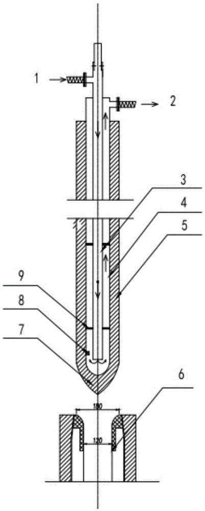
[0027] see figure 1 and figure 2 As shown, a slag buffer system with a flow control function in the present invention includes a slag cladding shell 17, a stopper, a stopper control mechanism 13, a slag drop pipe 10, a sliding nozzle and a control mechanism 12, and a liquid level monitoring device 14 and flow meter 11 .

[0028] The top of the slag ladle shell 17 has a slag inlet 15 and the bottom has one or more nozzles 6, and the slag ladle shell 17 is made of high temperature resistant material. The molten slag flows in from the slag inlet 15 above the slag ladle, and is temporarily stored in the slag ladle, and the molten slag flows from the slag drop pipe 10 at the bottom of the slag ladle shell 17 to the granulation system below.

[0029] A flow meter is installed on the outer wall of the slag falling pipe 10 to detect the slag flow in the pipe and feed back the detection signal to the stopper rod control mechanism 13 . When the flow rate is too large, the stopper ro...


PUM


Abstract

The invention discloses a slag buffering system with a flow control function. The slag buffering system comprises a slag ladle shell, stopper rods, stopper rod control mechanisms and slag falling pipes. A slag inlet is formed in the upper portion of the slag ladle shell, and a plurality of water openings are formed in the bottom of the slag ladle shell. The slag falling pipes with flow meters are arranged at the lower portions of the water openings. Each water opening is correspondingly provided with a stopper rod. The stopper rods are arranged over the corresponding water openings. The stopper rod control mechanisms are used for controlling the circulation area between the stopper rods and the water openings. Slag flows into a slag ladle from a slag inlet above the slag ladle and is stored in the slag ladle, and the slag flows out of the slag falling pipes from the water openings in the bottom of the slag ladle. The flow of the slag is controlled by controlling the circulation area through cooperation of the stopper rods and the water openings. The flow meters are arranged on the slag falling pipes to detect the flow of the slag, and detection signals are fed back to the stopper rod control mechanisms. According to the slag buffering system, the temporary slag storage function and the flow control function are achieved, the following pelletization process can be continuously and stably conducted on the slag, and the slag buffering system can be widely applied to a slag pelletization waste heat recycling system.

Description

technical field [0001] The invention relates to the technical field of slag waste heat recovery, in particular to a slag buffer system with a flow control function. Background technique [0002] China is currently the world's largest steel producer, and its steel output has remained the world's largest for 17 consecutive years. In 2014, China's pig iron output reached 711 million tons, accounting for about 60% of the world's total output. In the process of smelting pig iron, slag containing huge heat will be produced at the same time. The temperature of the molten slag is generally between 1400 and 1550 ° C, and each ton of slag contains (1260 to 1880) × 10 3 The sensible heat of kJ is equivalent to 60kg standard coal. Under the current ironmaking technology in my country, 0.3 tons of slag is produced for every ton of pig iron produced. Based on the current pig iron production in my country of 711 million tons, it can be converted into more than 213 million tons of slag, a...

Claims


Application Information

Patent Timeline
IPC IPC(8): C21B3/06
CPCC21B3/06Y02W30/50
Inventor 王树众孟海鱼陈林于鹏飞吴志强张忠清
Owner XI AN JIAOTONG UNIV
Why Eureka
Try Eureka