Part cleaning machine

A technology for cleaning machines and parts, applied in the field of parts cleaning, can solve the problems of low cleaning efficiency, insufficient cleaning power of parts cleaning machines, and low cleanliness of parts, and achieve the effects of improving cleaning degree, low toxicity and good fluidity

Inactive Publication Date: 2016-06-01
DONGGUAN QINGMAITIAN DIGITAL TECH
View PDF3 Cites 11 Cited by
  • Summary
  • Abstract
  • Description
  • Claims
  • Application Information

AI Technical Summary

Problems solved by technology

[0003] The invention aims to solve the technical problems of insufficient cleaning force, low cleaning efficiency and low cleanliness of parts in the prior art, and provides a parts cleaning machine

Method used


Image

  • Part cleaning machine
  • Part cleaning machine
  • Part cleaning machine

Examples


Embodiment Construction

[0023] The specific embodiment of the present invention will now be described in detail in conjunction with the accompanying drawings.

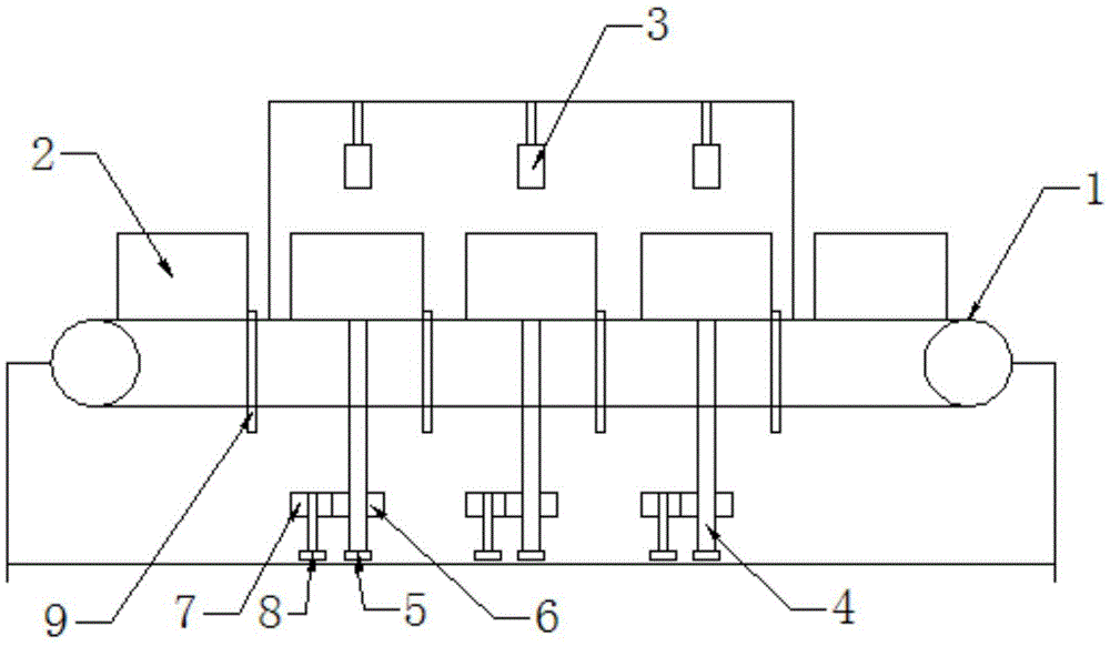
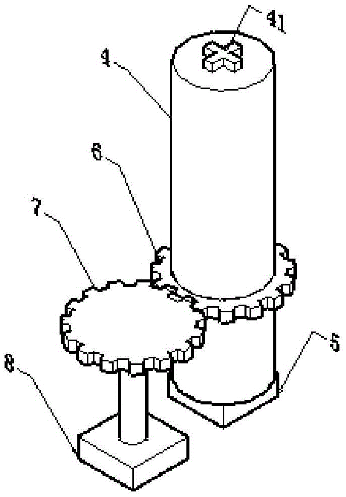
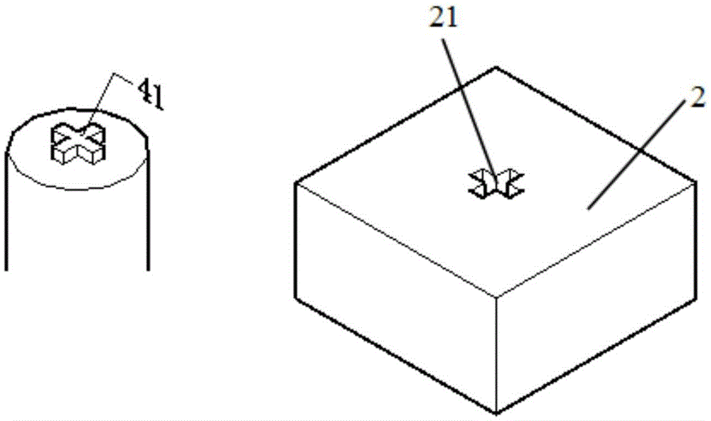
[0024] Such as figure 1 As shown, the parts washing machine of the present invention includes a conveyor belt 1, a material tray 2, and a rotary spraying device 3 located above the conveyor belt 1, and the spraying device 3 is filled with cleaning liquid. The below of the conveyer belt 1 directly below the spraying device 3 is provided with a support rod 4 . Such as figure 2 As shown, the top of the support rod 4 and the center of the bottom of the tray 2 have a locking mechanism that engages with each other, and a pressure cylinder 5 is arranged at the bottom of the support rod 4, and the pressure cylinder 5 can send the cylinder along the conveyor belt 1 to the sprayer in the vertical direction. The material tray 2 directly below the washing device 3 is jacked up, and a gear 6 is also fixedly arranged on the support rod 4, and the gear ...


PUM


Abstract

The invention discloses a part cleaning machine. The part cleaning machine comprises a conveyor belt, material discs and rotary spray washing devices located above the conveyor belt. The spray washing devices are filled with cleaning liquid. Supporting rods are arranged under the parts, right below the spray washing devices, of the conveyor belt. The top ends of the supporting rods and the centers of the bottoms of the corresponding material discs are provided with mutually engaged locking mechanisms. The bottom of each supporting rod is provided with a pressure cylinder. The pressure cylinder can jack up the corresponding material disc conveyed to the position right below the corresponding spray washing device along the conveyor belt in the perpendicular direction. A gear is further fixedly arranged on each supporting rod, and each gear is engaged with another gear driven by a motor so as to drive the corresponding material disc to rotate. By the adoption of the part cleaning machine disclosed by the invention, the cleaning degree is high, and the cleaning efficiency is high.

Description

technical field [0001] The invention relates to the field of parts cleaning, in particular to a parts cleaning machine. Background technique [0002] During the production and processing of precision hardware parts, the parts need to go through multiple processing procedures from the blank to the finished product, such as turning, cutting, drilling, grinding, milling, planing, etc. After the parts are processed, there will be oil stains and debris on the surface and inside the holes. Impurities such as chips, which affect the further processing and use of parts, need to be cleaned. Existing parts cleaning generally uses a high-pressure air gun to blow off particles such as impurities and debris on the surface of the parts and in the holes, and then sprays cleaning fluid to the parts through a high-pressure liquid spray gun. However, the above-mentioned cleaning process is relatively complicated, and special personnel need to be arranged to be responsible for cleaning. The w...

Claims


Application Information

Patent Timeline
Patent Type & Authority Applications(China)
IPC IPC(8): C23G5/024C23G5/04B08B3/02
CPCC23G5/024B08B3/022B08B2203/0217C23G5/04
Inventor 刘丽蓉
Owner DONGGUAN QINGMAITIAN DIGITAL TECH
Why Eureka
Try Eureka