
Mould for manufacturing housing unit from inside to outside in manner of integral forming

A technology for inner molds and houses, which is applied to the preparation of ceramic molding cores, ceramic molding mandrels, and building components on site. It can solve the problems of many connection nodes, high construction costs, and large material consumption, and achieve satisfactory functions. Demand, rich shape and texture, and the effect of improving production efficiency

Active Publication Date: 2016-06-01
ZHUO DA NEW MATERIAL TECH GRP
View PDF5 Cites 5 Cited by
  • Summary
  • Abstract
  • Description
  • Claims
  • Application Information

AI Technical Summary

Problems solved by technology

[0005] Both of these two methods of operation have problems such as many construction processes and large material consumption, and the construction cost remains high. Moreover, due to the large number of connection nodes and uneven quality, the integrity of the building is not high; and most of the completed buildings are rough houses. , the residents all need to carry out secondary decoration, which increases the burden and material consumption

Method used


Image

  • Mould for manufacturing housing unit from inside to outside in manner of integral forming
  • Mould for manufacturing housing unit from inside to outside in manner of integral forming
  • Mould for manufacturing housing unit from inside to outside in manner of integral forming

Examples


Embodiment 1

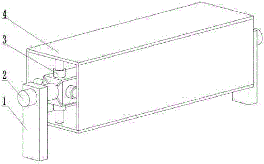
[0024] Combine below Attached picture The mold provided by the present invention is described in detail.

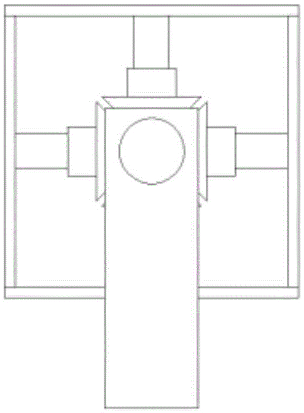
[0025] The mold of the present invention is composed of a support 1, a central shaft 2, a hydraulic rod 3, an inner mold cylinder 4, a printing platform guide rail 5, a forming unit cylinder 6, a printing platform support 7, a printing platform 8, a printing flat head 9 and a feeding pipe 10.

[0026] The mold support 1 is composed of two columns with one end provided with a through hole perpendicular to the axis, the two ends of the central axis 2 pass through the through hole of the support 1 respectively, and the inner mold cylinder 4 is coaxially sleeved outside the central axis 2. The platform 8 is arranged on the outer side of the inner mold barrel 4; a hydraulic rod 3 perpendicular to the axis is arranged between the central axis 2 and the inner mold barrel 4.

Embodiment 2

[0028] The three groups of hydraulic rods 3 are respectively arranged at the two ends and the middle of the central axis 2 , corresponding to the two ends and the middle of the inner wall of the inner mold barrel 4 . Each group consists of 3 hydraulic rods arranged radially and equidistantly on the central axis 2.

Embodiment 3

[0030] The printing platform guide rails 5 are longitudinally arranged on both sides of the inner mold cylinder 4 in parallel, and the pulleys arranged at both ends of at least two support members of the printing platform across the inner mold cylinder 4 are arranged on the guide rails.


PUM


Abstract

The invention provides a mould for manufacturing a housing unit from inside to outside in manner of integral forming. The housing unit is an integrated housing unit comprising walls, a floor and a roof; the mould is characterized by comprising a mould support (1), a center shaft (2), an inner mould tube (4) and a printing platform (8), wherein the mould support (1) consists of two pillars in each of which one end a through hole perpendicular to an axis is formed, two ends of the center shaft (2) separately penetrate through the through holes, and the inner mould tube (4) is coaxial with the center shaft; hydraulic rods (3) perpendicular to the center shaft (2) are arranged between the center shaft (2) and the inner mould tube (4). The housing unit manufactured by the technical solution provided by the invention is manufactured by layer-by-layer high-pressure printing with mortar and the mould in order from the inner wall to the outer wall of the housing unit; not only can one unit be used as a single living room, but also a plurality of units can be assembled into an integral suite having functional spaces, such as a plurality of living rooms, a kitchen and a toilet; the inner wall and the outer wall of the housing unit can be processed into various texture surfaces according to needs of a user.

Description

technical field [0001] The invention relates to a mold for integrally forming housing units, in particular to a mold for preparing integrally forming housing units for one family to live in. Background technique [0002] Molds are various molds and tools used in industrial production for injection molding, blow molding, extrusion, die-casting or forging forming, smelting, stamping and other methods to obtain the required products. [0003] The mold is a precision tool with a complex shape and bears the bulging force of the billet. It has high requirements for structural strength, stiffness, surface hardness, surface roughness and machining accuracy. The development level of mold production is one of the important symbols of the level of mechanical manufacturing. [0004] The traditional house construction method is to use a large number of masons' manual and semi-mechanized operations on the construction site to accumulate construction materials such as mud, bricks, concrete...

Claims


Application Information

Patent Timeline
IPC IPC(8): E04G21/02E04G21/04E04G11/02
CPCB28B7/30E04G11/02E04G21/02E04G21/04
Inventor 杨卓舒纪勇程长友李利民许利剑
Owner ZHUO DA NEW MATERIAL TECH GRP
Learn More