low permeability reservoir co 2 Method for Determining Limit Well Spacing of Flooding Technology

A definite method and low-permeability technology, applied in wellbore/well components, earthwork drilling and production, production fluids, etc., can solve problems such as low recovery, inability to achieve displacement, low permeability of low-permeability reservoirs, etc., to achieve Broad prospects for popularization and application, increasing economically recoverable reserves, and strengthening the effect of resource base development

Active Publication Date: 2018-01-16
CHINA PETROLEUM & CHEM CORP +1
View PDF6 Cites 0 Cited by
  • Summary
  • Abstract
  • Description
  • Claims
  • Application Information

AI Technical Summary

Problems solved by technology

Laboratory experiments have shown that due to the low permeability of low-permeability reservoirs, there is a start-up pressure gradient in carbon dioxide flooding, and effective displacement can only be achieved if the displacement pressure gradient between injection and production wells is greater than the start-up pressure gradient, so there is a limit injection-production well spacing
If the injection-production well spacing is too small, it is easy to cause premature gas channeling and affect the development effect; if the injection-production well spacing is too large, the displacement between injection-production wells cannot be realized, and the production wells are elastically developed, with low recovery
At the same time, carbon dioxide is affected by pressure between injection and production wells, and there will be three states: miscible, miscible and immiscible engineering, and immiscible. There is a large gap between the start-up pressure gradient and the technical limit well spacing of these three states

Method used


Image

  • low permeability reservoir co  <sub>2</sub> Method for Determining Limit Well Spacing of Flooding Technology
  • low permeability reservoir co  <sub>2</sub> Method for Determining Limit Well Spacing of Flooding Technology
  • low permeability reservoir co  <sub>2</sub> Method for Determining Limit Well Spacing of Flooding Technology

Examples


Embodiment Construction

[0032] In order to make the above-mentioned and other objects, features and advantages of the present invention more obvious and understandable, preferred embodiments are listed below in conjunction with the accompanying drawings, which are described in detail as follows.

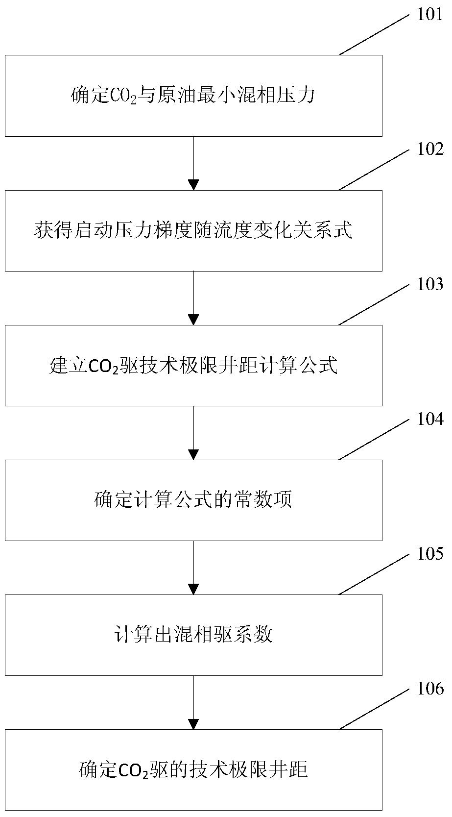
[0033] Such as figure 1 As shown, figure 1 It is the low permeability reservoir CO of the present invention 2 A flowchart of a specific embodiment of the method for determining the limit well spacing of the flooding technology.

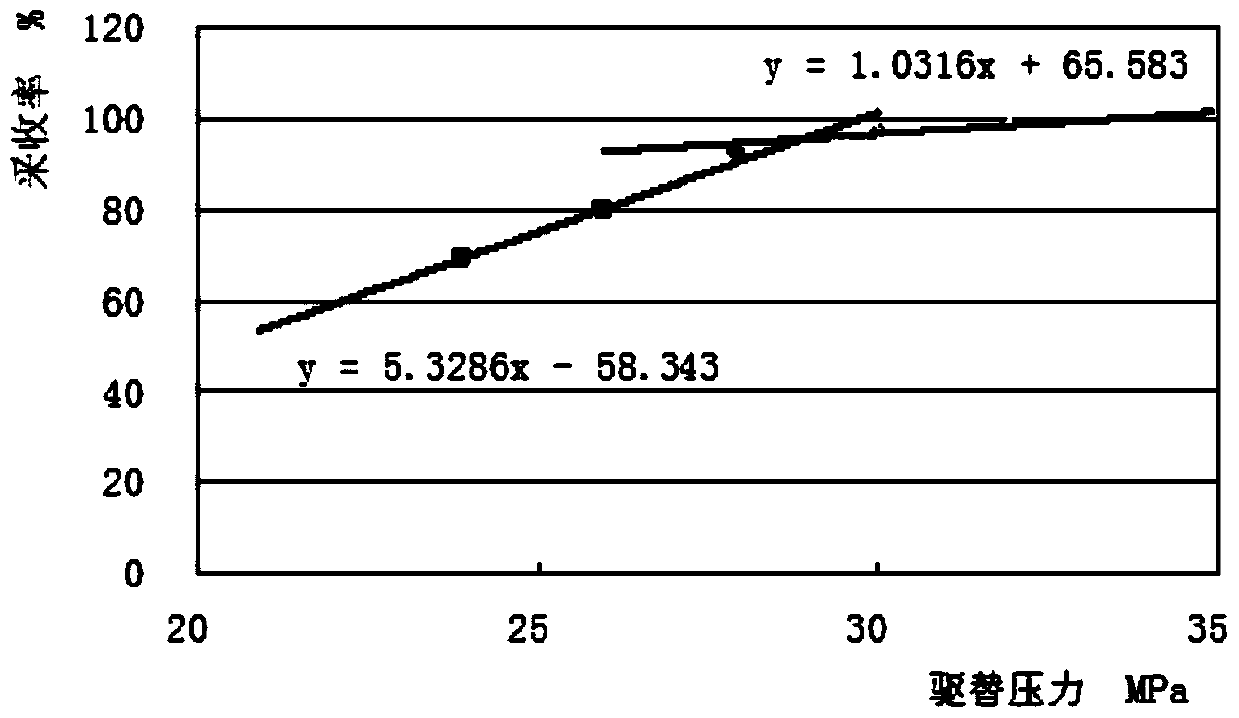
[0034] In step 101, select 5 different displacement pressures to carry out the long thin tube displacement experiment. First, the thin tube model is saturated with the formation crude oil under the formation temperature and displacement pressure, and the back pressure is controlled by the back pressure valve as required for the experiment. pressure. After the system is balanced, use 9.00cm 3 / h inject CO 2 Displacement with gas, measure the oil and gas fluid produced during the displace...


PUM


Abstract

The invention provides a CO2 drive technological limit well spacing determination method for a low-permeability oil reservoir. The method comprises the steps that the minimum miscible pressure of CO2 and crude oil is determined through a long-thin pipe displacement test; through a rock core displacement test, with the combination of the minimum miscible pressure of the crude oil, the relational expression of the change of starting pressure gradient along with fluidity under the miscible phase and immiscible phase conditions is determined; a calculation formula of a CO2 drive technological limit oil supply radius is established through an oil reservoir engineering method; through a site test method or an oil reservoir numerical simulation method, stratum pressure distribution conditions are obtained, a miscible phase area and an immiscible phase area are determined, and the proportionality coefficient of the miscible phase area and the immiscible phase area is calculated; and through a calculation formula of CO2 drive technological limit well spacing, stratum technological limit well spacing under the current condition is obtained through calculation. According to the CO2 drive technological limit well spacing determination method for the low-permeability oil reservoir, oil field potential is further exploited, economically recoverable reserves are increased greatly, the resource exploitation basis is enhanced, and the crude oil recovery ratio is further increased.

Description

Technical field [0001] The invention relates to a method for calculating the spacing between injection and production wells in oilfield development, in particular to a low permeability oil reservoir CO 2 Method for determining the limit well spacing of flooding technology. Background technique [0002] With the continuous advancement of exploration and development technologies, low-permeability reservoirs, regardless of their reserves and production, play an increasingly important role in my country’s oil development. However, due to reservoir conditions, the development effect is relatively poor, and carbon dioxide is a superior flooding Oil agent, used for oil displacement, can greatly increase the production rate and recovery rate of this type of reservoir, and its development effect can be significantly improved. [0003] The well pattern and spacing are the key to the design of carbon dioxide flooding schemes, especially the injection-production well spacing has an important in...

Claims


Application Information

Patent Timeline
Patent Type & Authority Patents(China)
IPC IPC(8): E21B43/16E21B43/14
Inventor 吕广忠杨勇郭迎春杜玉山任允鹏张东张建乔李绍杰
Owner CHINA PETROLEUM & CHEM CORP
Why Eureka
Try Eureka