Ultrasonic wave residual stress test device
A technology of residual stress and testing equipment, applied in force/torque/work measuring instruments, measuring devices, instruments, etc., can solve the problems of limiting the development of ultrasonic residual stress testing methods, affecting the testing accuracy of ultrasonic residual stress testing methods, etc. The effect of non-destructive correction and improving test accuracy
- Summary
- Abstract
- Description
- Claims
- Application Information
AI Technical Summary
Problems solved by technology
Method used
Image
Examples
specific Embodiment approach
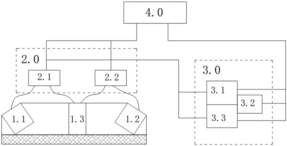
[0057] figure 1 Shown, a specific embodiment of the present invention is: an ultrasonic residual stress testing equipment, including ultrasonic transducer group, multi-channel ultrasonic card 2.0, signal processing board 3.0 and control terminal 4.0, the ultrasonic transducer The group includes a critical refraction longitudinal wave excitation probe 1.1 and a critical refraction longitudinal wave receiving probe 1.2, and its structural characteristics are: the ultrasonic transducer group also includes a device that can transmit ultrasonic longitudinal wave signals to the test area of the weldment to be tested and receive longitudinal wave echo signals Longitudinal wave flat probe 1.3, used for attenuation test in the test area of the weldment to be tested;
[0058] The multi-channel ultrasonic card 2.0 includes:
[0059] The ultrasonic signal excitation module 2.1 is connected to the critical refraction longitudinal wave excitation probe 1.1 and the longitudinal wave fla...
Embodiment 2
[0069] An ultrasonic residual stress testing device, including an ultrasonic transducer group, a multi-channel ultrasonic card 2.0, a signal processing board 3.0 and a control terminal 4.0, the ultrasonic transducer group includes a critical refraction longitudinal wave excitation probe 1.1 and a critical refraction longitudinal wave receiving Probe 1.2, its structural features are: the ultrasonic transducer group also includes a longitudinal wave flat probe 1.3 that can transmit ultrasonic longitudinal wave signals to the test area of the weldment to be tested and receive longitudinal wave echo signals, and is used for testing the weldment to be tested Attenuation test in the area;
[0070] The multi-channel ultrasonic card 2.0 includes:
[0071] The ultrasonic signal excitation module 2.1 is connected to the critical refraction longitudinal wave excitation probe 1.1 and the longitudinal wave flat probe 1.3, and is used to excite the critical refraction longitudinal wave ex...
Embodiment 3
[0080] An ultrasonic residual stress testing device, including an ultrasonic transducer group, a multi-channel ultrasonic card 2.0, a signal processing board 3.0 and a control terminal 4.0, the ultrasonic transducer group includes a critical refraction longitudinal wave excitation probe 1.1 and a critical refraction longitudinal wave receiving Probe 1.2, its structural features are: the ultrasonic transducer group also includes a longitudinal wave flat probe 1.3 that can transmit ultrasonic longitudinal wave signals to the test area of the weldment to be tested and receive longitudinal wave echo signals, and is used for testing the weldment to be tested Attenuation test in the area;
[0081] The multi-channel ultrasonic card 2.0 includes:
[0082] The ultrasonic signal excitation module 2.1 is connected to the critical refraction longitudinal wave excitation probe 1.1 and the longitudinal wave flat probe 1.3, and is used to excite the critical refraction longitudinal wave ex...
PUM
 Abstract
Description
Claims
Application Information
 - R&D
- Intellectual Property
- Life Sciences
- Materials
- Tech Scout
- Unparalleled Data Quality
- Higher Quality Content
- 60% Fewer Hallucinations
Browse by: Latest US Patents, China's latest patents, Technical Efficacy Thesaurus, Application Domain, Technology Topic, Popular Technical Reports.
© 2025 PatSnap. All rights reserved.Legal|Privacy policy|Modern Slavery Act Transparency Statement|Sitemap|About US| Contact US: help@patsnap.com

