Electromagnetic ultrasonic probe

An electromagnetic ultrasonic and magnet technology, which is applied in the field of industrial measurement, can solve the problems of large volume, large sliding resistance, and affect the detection accuracy of the electromagnetic ultrasonic probe.

Active Publication Date: 2016-06-01
HUZHOU CITY SPECIAL EQUIP INSPECTION INST
View PDF6 Cites 9 Cited by
  • Summary
  • Abstract
  • Description
  • Claims
  • Application Information

AI Technical Summary

Problems solved by technology

[0003] However, traditional electromagnetic ultrasonic probes use permanent magnets with strong magnetism to generate excitation magnetic fields. Therefore, even in the non-working state, the probes still have strong magnetic adsorption force on ferromagnetic workpieces. Be careful, and because it is necessary to ensure that the electromagnetic ultrasonic probe needs to have a certain lift-off distance during detection (the distance between the bottom of the probe and the surface of the workpiece)
Therefore, in the prior art, the paired pulley assembly is often used as a mobile trolley for probe detection on the surface of the workpiece, and the lifting distance is realized through the wheel height of the pulley. Similar to the electromagnetic ultrasonic probe with this structure, the disadvantages are: 1. Electromagnetic The volume of the ultrasonic probe is large; 2. Due to the magnetic adsorption force, the sliding resistance generated by the contact between the pulley and the surface of the workpiece is still very large, and it is inconvenient to move; 3. Since the pulley is on both sides with a certain distance from the actual detection surface of the probe, the wheel The lift-off distance under high support is inconsistent with the actual distance between the probe head and the workpiece surface, or may fluctuate, making the data returned by the coil under the magnet inaccurate and affecting the detection accuracy
However, no matter what kind of auxiliary means is superimposed on the electromagnetic ultrasonic detection technology, or the structural design of the electromagnetic ultrasonic probe shown in the prior art, it is applied to the component detection of plane or tubular structures. The workpiece, because the distance between the electromagnetic ultrasonic probe and the curved surface cannot be controlled, the use of the electromagnetic ultrasonic probe is greatly limited

Method used


Image

  • Electromagnetic ultrasonic probe
  • Electromagnetic ultrasonic probe
  • Electromagnetic ultrasonic probe

Examples


Embodiment Construction

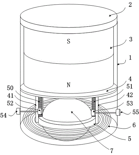
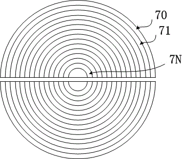
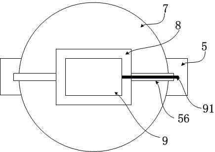
[0022] Such as figure 1 The shown electromagnetic ultrasonic probe comprises a shell 1, a signal processing module 2 is installed on the upper end of the shell 1, a magnet 3 is arranged inside, a coil 6 is arranged at the lower part of the magnet 3, and a ball mechanism is arranged in the center space of the coil 6, and the ball mechanism includes a ball 7. The constraining ring 5 and the ball 7 are limited to roll in the constraining ring 5, and the fixing columns 41 and 42 are fixed at the lower part of the partition 4; If no height adjustment part is added, the length of the ball protruding from the lower part of the probe is the lifting distance between the coil 6 and the workpiece to be measured. But the optimized design that present embodiment proposes is to have vertical rack 50 and 51 on confinement ring 5, and vertical rack 50 and 51 are respectively slidingly connected with fixed column 41 and 42, and gear 52 and 53 are connected with vertical rack 50 and 51 respecti...


PUM


Abstract

The invention discloses an electromagnetic ultrasonic probe. The electromagnetic ultrasonic probe comprises a shell, a signal processing module, a magnet and a coil below the magnet, wherein a ball bearing mechanism is arranged inside a central space of the coil; the ball bearing mechanism comprises a ball, a restraining ring and fixing posts; the ball is limited inside the restraining ring for rolling; the restraining ring is limited by the fixing posts inside the central space of the coil. The lift-off distance between the electromagnetic ultrasonic probe and a workpiece can be regulated according to the length of a part, protruding out of the bottom of the probe, of the ball, and during detection, the lift-off distance can keep constant no matter the surface of the workpiece is a curved surface or a plane; point contact between the electromagnetic ultrasonic probe and the surface of the workpiece is achieved, so that influence of a magnetic attractive force of the electromagnetic ultrasonic probe on movement becomes smaller and the probe moves more smoothly.

Description

technical field [0001] The invention relates to the technical field of industrial measurement, in particular to an electromagnetic ultrasonic probe. technical background [0002] Electromagnetic ultrasonic (EMAT) non-destructive testing technology is different from piezoelectric sensors, because it does not require couplant, and does not need to process and contact the surface of the workpiece, it can detect cracks and thicknesses in the surface of the workpiece, so it is the reliability of industrial equipment. and important equipment for safety testing. [0003] However, traditional electromagnetic ultrasonic probes use permanent magnets with strong magnetism to generate excitation magnetic fields. Therefore, even in the non-working state, the probes still have strong magnetic adsorption force on ferromagnetic workpieces. Be careful, and because it is necessary to ensure that the electromagnetic ultrasonic probe needs to have a certain lift-off distance (the distance betw...

Claims


Application Information

Patent Timeline
Patent Type & Authority Applications(China)
IPC IPC(8): G01N27/83G01B7/06
CPCG01B7/10G01N27/725G01N27/83
Inventor 谢国利钦峰王宏夏临明
Owner HUZHOU CITY SPECIAL EQUIP INSPECTION INST
Why Eureka
Try Eureka