
Reinforcement method of concrete deep beam

A concrete and deep beam technology, applied in special data processing applications, instruments, electrical digital data processing, etc., can solve problems such as incomprehension, complex force, difficult to master, etc., and achieve the effect of improving accuracy and accuracy

Inactive Publication Date: 2016-06-01
CE CENT FOR ENG RES TEST & APPRAISAL +1
View PDF5 Cites 8 Cited by
  • Summary
  • Abstract
  • Description
  • Claims
  • Application Information

AI Technical Summary

Problems solved by technology

In order to resist various damages, the reinforcement of deep beams is more complicated
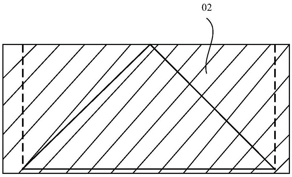
[0003] At present, the code recommends to adopt the section internal force method for design. In the design of concrete deep beams, the designed deep beam structure is generally divided into B area (non-disturbed area) 01 and D area (disordered area) 02 according to Saint-Venant's theorem, such as Figure 1a and Figure 1b shown, where Figure 1a and Figure 1b It is the schematic diagram of the structure after the deep beam structure is divided into B area and D area. For the area outside the range of the beam height in the longitudinal direction of the loading position (B area, also known as the non-turbulent area) conforming to the assumption of the plane section, the internal force of the section can be used For the area that does not conform to the assumption of the plane section within the range of beam height (D area, also known as the disordered area), the force is complicated.
[0004] If the cross-sectional internal force method is used for force analysis and reinforcement of D area, the calculation accuracy is poor
The commonly used reinforcement calculations for the D area of ​​deep beam structures are obtained from experimental analysis and referring to past experience. The disadvantages of this method are: first, the error may be large, and most of them are conservative; second, the concept of mechanics is unclear, difficult to understand

Method used


Image

  • Reinforcement method of concrete deep beam
  • Reinforcement method of concrete deep beam
  • Reinforcement method of concrete deep beam

Examples


Embodiment Construction

[0033] The following will clearly and completely describe the technical solutions in the embodiments of the present invention with reference to the accompanying drawings in the embodiments of the present invention. Obviously, the described embodiments are only some, not all, embodiments of the present invention.

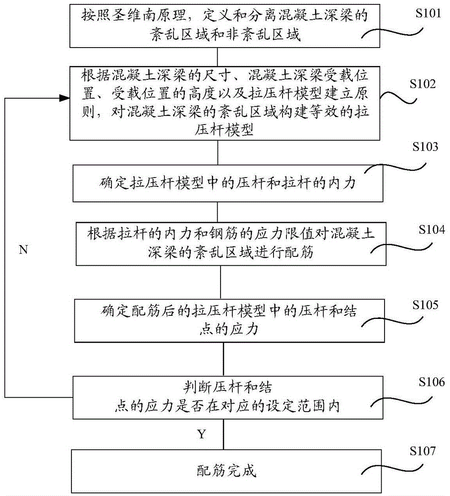
[0034] like figure 2 as shown, figure 2 The flow chart of the reinforcing method for concrete deep beams provided by the embodiment of the present invention, the present invention provides a method for reinforcing concrete deep beams, including:

[0035] Step S101: According to Saint-Venant's principle, determine the disordered region and the non-disturbed region of the concrete deep beam;

[0036] Step S102: according to the size of the concrete deep beam, the loaded position of the concrete deep beam, the height of the loaded position and the establishment principle of the tension and compression bar model, construct an equivalent tension and compression bar mod...


PUM


Abstract

The invention discloses a reinforcement method of a concrete deep beam, and aims at improving the reinforcement correctness of the concrete deep beam. The reinforcement method comprises the following steps: S101, determining a disordered area and a non-disordered area of the concrete deep beam according to a saint venant principle; S102, constructing an equivalent strut-and-tie model for the disordered area of the concrete deep beam; S103, determining the internal forces of a strut bar and tie bar in the strut-and-tie model; S104, reinforcing the disordered area of the concrete deep beam according to the internal force of the tie bar and stress limiting value of a reinforcing steel bar; S105, determining the stresses of the strut bar in the reinforced strut-and-tie model and a knot; S106, judging the stresses of the strut bar and the knot are in a corresponding set range, if both the stresses of the strut bar and the knot are in the corresponding set range, executing the step S107, and if the stresses of the strut bar and / or the knot are not in the corresponding set range, executing the step S102; and S107, finishing the reinforcement.

Description

technical field [0001] The invention relates to the technical field of construction engineering, in particular to a reinforcement method for deep concrete beams. Background technique [0002] "Code for Design of Concrete Structures" (GB50010-2002) stipulates that simply supported beams with a ratio of span to height l / h≤2 and continuous beams with l / h≤2.5 are deep beams. Due to the large size of the deep beam structure and the complex force of the internal system, there are many types of failure of the deep beam. There are three main failure forms of deep beams: one is bending failure; the other is shear failure; the third is local compression or anchorage failure. In order to resist various damages, the reinforcement of deep beams is more complicated. [0003] At present, the code recommends to adopt the section internal force method for design. In the design of concrete deep beams, the designed deep beam structure is generally divided into B area (non-disturbed area) 01 ...

Claims


Application Information

Patent Timeline
IPC IPC(8): G06F19/00
CPCG16Z99/00
Inventor 王娟娟刘立渠翟传明吴晓媛陈美多李晨
Owner CE CENT FOR ENG RES TEST & APPRAISAL
Learn More