Moving platform laser infrared fusion detection and recognition system

A technology for identifying systems and lasers, applied in the direction of processor architecture/configuration, etc., to achieve the effect of improving system parallelism

Active Publication Date: 2016-06-01
HUAZHONG UNIV OF SCI & TECH
View PDF4 Cites 8 Cited by
  • Summary
  • Abstract
  • Description
  • Claims
  • Application Information

AI Technical Summary

Problems solved by technology

[0011] Aiming at the defects of the prior art, the present invention provides a laser-infrared fusion detection and recognition system, which aims to solve the existing problems

Method used


Image

  • Moving platform laser infrared fusion detection and recognition system
  • Moving platform laser infrared fusion detection and recognition system
  • Moving platform laser infrared fusion detection and recognition system

Examples


Embodiment Construction

[0047] In order to make the object, technical solution and advantages of the present invention clearer, the present invention will be further described in detail below in conjunction with the accompanying drawings and embodiments. It should be understood that the specific embodiments described here are only used to explain the present invention, not to limit the present invention. In addition, the technical features involved in the various embodiments of the present invention described below can be combined with each other as long as they do not constitute a conflict with each other.

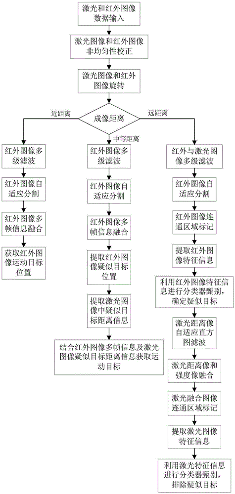
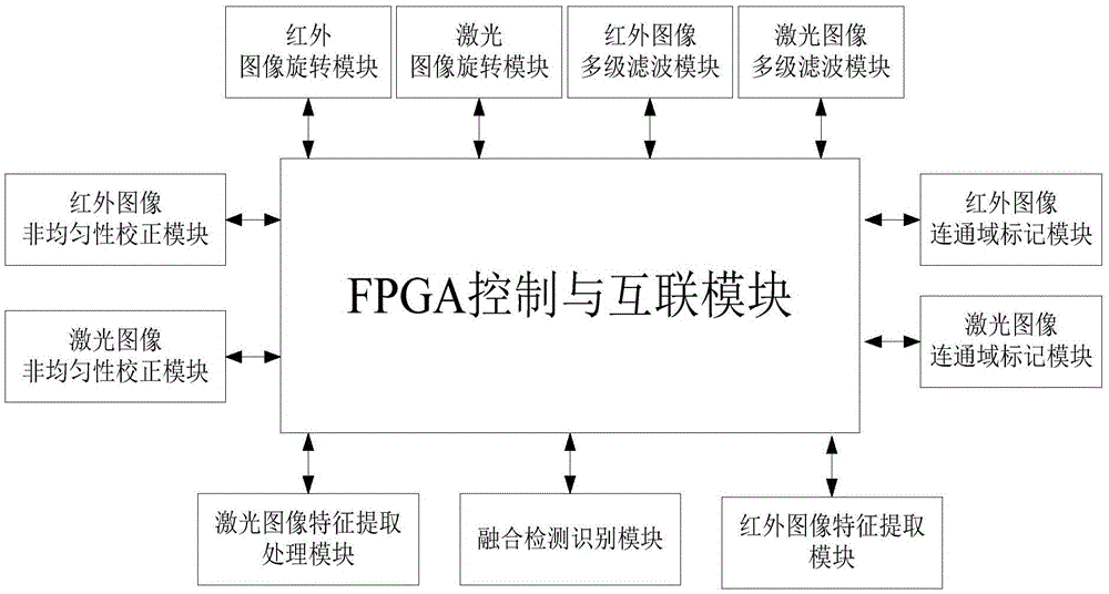
[0048] Such as figure 2 As shown, in terms of function realization, the laser infrared fusion detection and recognition system can be divided into image non-uniformity correction module, image rotation module, multi-stage filtering module, connected domain marking module, target detection and feature recognition control module, and interconnection realized by FPGA. module.

[0049] The image ...


PUM


Abstract

The invention discloses a laser infrared fusion detection and recognition system, which comprises a nonuniformity correction SoC chip, an image rotation ASIC chip, a multistage filtering ASIC chip, a connected component labeling ASIC chip, a main DSP, a slave DSP, a main FPGA processor and a slave FPGA processor, wherein the slave FPGA processor controls each ASIC/SoC chip to complete laser and infrared image pretreatment; and the main FPGA processor controls the main DSP, the slave DSP and the labeling ASIC to help to complete long-distance, middle-distance and near-distance target fusion detection and recognition. The parallelism and the real-time performance of the system are improved, and power consumption of the system can be effectively reduced.

Description

technical field [0001] The invention belongs to the technical field of fusion detection and recognition of infrared images and laser images, and in particular relates to a real-time system for detection and recognition of laser infrared fusion of a moving platform. Background technique [0002] Aircraft automatic target recognition is usually a process in which the imaging platform moves from far to near relative to the target. At long distances, infrared imaging target recognition plays a dominant role, and laser imaging target recognition does not work temporarily. At a long distance, the infrared imaging target is mostly a point source target with less information; at a medium distance, the infrared imaging target is mostly a spotty target, and its image size, simple shape and image gray distribution information can be used. Laser imaging can Utilize range images for ranging and provide distance information for infrared imaging targets; finally, at a relatively short dist...

Claims


Application Information

Patent Timeline
IPC IPC(8): G06T1/20
CPCG06T1/20
Inventor 张天序杨智慧桑红石黄伟陈琨郑畅李欢
Owner HUAZHONG UNIV OF SCI & TECH
Why Eureka
Try Eureka