
Electroluminescent display panel, manufacturing method therefor, and display apparatus

A technology of electroluminescence display and manufacturing method, which is applied to circuits, electrical components, electrical solid devices, etc., to achieve the effect of improving light extraction efficiency and improving extraction efficiency

Active Publication Date: 2016-06-01
BOE TECH GRP CO LTD
View PDF6 Cites 16 Cited by
  • Summary
  • Abstract
  • Description
  • Claims
  • Application Information

AI Technical Summary

Problems solved by technology

[0003] The purpose of the embodiments of the present invention is to provide an electroluminescent display panel, its manufacturing method and display device, which are used to solve the problem of improving the light extraction efficiency of organic light emitting display devices and improving the flexibility of organic light emitting display devices

Method used

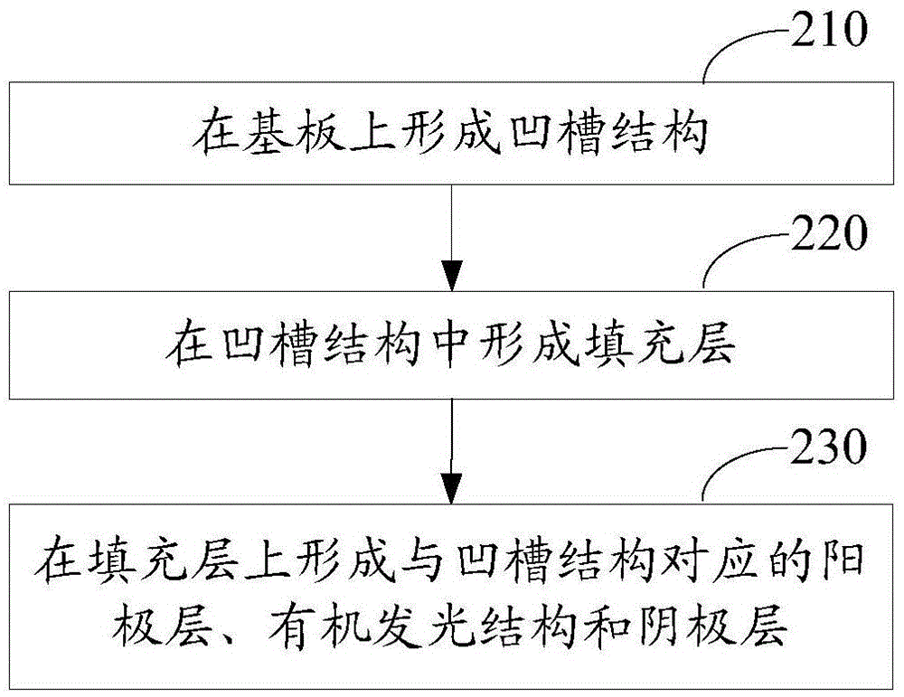

Image

  • Electroluminescent display panel, manufacturing method therefor, and display apparatus
  • Electroluminescent display panel, manufacturing method therefor, and display apparatus
  • Electroluminescent display panel, manufacturing method therefor, and display apparatus

Examples


Embodiment Construction

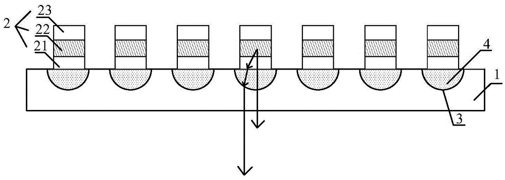
[0039] An electroluminescent display panel, its manufacturing method and display device provided by the present invention will be described in more detail below with reference to the accompanying drawings and embodiments. The thickness of each film layer in the drawings does not represent the actual thickness and proportion of the electroluminescent display panel.

[0040] Such as figure 1 As shown, the embodiment of the present invention provides an electroluminescent display panel, including a substrate 1 and a plurality of OLEDs 2 on the substrate 1; the OLED 2 includes a transparent anode layer 21 on the substrate 1, and an organic organic A light-emitting structure 22, and a cathode layer 23 located on the organic light-emitting structure 22, the cathode layer 23 is a reflective layer;

[0041] There is a groove structure 3 corresponding to the organic light-emitting structure 22 on the contact surface between the substrate 1 and the anode layer 21;

[0042] A transpare...


PUM


Abstract

Embodiments of the invention disclose an electroluminescent display panel, a manufacturing method therefor, and a display apparatus. The electroluminescent display panel comprises a substrate and multiple OLEDs positioned on the substrate, wherein each OLED comprises a transparent positive electrode layer positioned on the substrate, an organic light emitting structure positioned on the positive electrode layer, and a negative electrode layer positioned on the organic light emitting structure; the negative electrode layer is a reflecting layer; a groove structure corresponding to the organic light emitting structure is arranged on the contact surface between the substrate and the positive electrode layer; a transparent filling layer is arranged in the groove structure; the upper surfaces of the filling layer and the substrate are on the same horizontal plane; and the refractive index of the filling layer is greater than that of the positive electrode layer, and is different from that of the substrate. Under the refraction of the groove structures, the incident angle of the light from each organic light emitting structure to the substrate is reduced, so that the probability of total reflection of the light entering the substrate from the positive electrode layer is lowered, and the extraction efficiency of the light from each organic light emitting structure is improved; and in addition, the flexibility of the display panel is not lowered.

Description

technical field [0001] The invention relates to the field of display technology, in particular to an electroluminescence display panel, a manufacturing method thereof and a display device. Background technique [0002] At present, organic light-emitting display devices are the mainstream development direction of the next-generation display and lighting technology, and have the advantages of active light emission, wide color gamut, fast response, wide viewing angle, high contrast ratio, and planarization. In order to improve the light extraction efficiency of organic light-emitting display devices, one method is internal extraction, which is mainly to attach a scattering layer or a microlens film layer on the light-emitting surface of the substrate to reduce the total reflection from the glass substrate to the air; one method is External extraction, introducing a light-scattering layer inside the organic light-emitting display device, such as introducing a light-scattering la...

Claims


Application Information

Patent Timeline
Patent Type & Authority Applications(China)
IPC IPC(8): H01L27/32H01L51/56H10K99/00
CPCH10K71/00H10K59/17H10K59/873H10K59/879H10K77/111H10K59/10H10K50/805H10K50/844H10K50/858
Inventor 王丹张微
Owner BOE TECH GRP CO LTD
Learn More